
I’m pursuing yet another certification, this time the IIBA‘s CBAP, for Certified Business Analysis Professional. I chose a 35-hour training course run as a series of interactive webinars over seven successive weekend days and during the second session this past Sunday we ended up discussing several of the 50 techniques used by Business Analysts during each phase of an effort. The students were asked to each take a separate technique (we cover a few each session) and then talk on it for ten minutes or so. I was assigned the topic of Interface Analysis.
Since I’ve spent many years working on such things I observed that I was either the best possible choice to discuss that subject — or the worst — depending on your level of enthusiasm. My enthusiasm for this particular subject is high, so I took the opportunity to describe a few things from my website (we could share screens and all interact via audio and video), mostly on this page where I describe how my experience across many industries has led me to be a well-rounded systems or process analyst in the general sense. Come to think of it, I probably spent most of my time on this page, where I describe my experience as a system architect.
I don’t remember if I had time to describe any material to the group beyond the one page but I know that I discussed a few subjects, whether explicitly or implicitly. I’ll describe my clarified thoughts here.
- Interfaces can be used to connect:
- processes within a single machine: via shared memory, semaphores, or other sorts of messaging
- processes on separate machines: via serial, fiber optic, and hardwired and wireless network protocols like TCP/IP
- processes on separate networks: via routers and long-distance connections
- users with user interfaces of various sorts: using software GUIs and hardware switches, buttons, knobs, and so on
- logical operations within processes: information passed between logical blocks of code or representations as parameters and objects
- The electrical protocol and media is distinct from the information protocol.
- RS-232 and RS-485 are examples of serial protocols, and these describe a certain set of electrical connections and signalling used to send and receive information. Ethernet is a standard networking protocol, and wired and several wireless standards exist. Arduino boards use their own serial protocol for wireless communications distinct from WiFi and TCP/IP. Optical fiber communications have their own methodology. BACnet is commonly used for building control systems.
- HTML and XML are examples of information protocols. These can be transmitted across many different types of hardware connections, though of course TCP/IP is the most common. American Auto-Matrix publishes a protocols they call PUP (Public Unitary Protocol) and PHP (Public Host Protocol) that describe standard message formats typically transmitted over RS-232 and RS-485 connections. These are used to control, configure, and record data on networks of unit controllers attached to host controllers. An almost infinite variety of standalone message formats are defined for individual applications and I wrote many different versions.
- Interfaces need to ensure logical consistency across time. Mutexes are one way of ensuring this.
- Communications need to be checked for potential errors. A system I supported for Inductotherm used CRC checks to verify the accuracy and integrity of their serial messages.
- Our course instructor felt it necessary to observe that interfaces should be kept as simple as possible. This is true, and in my enthusiasm to complete a comprehensive information dump with minimum preparation I had neglected to mention it. It should also be recognized, however, that they should be as simple as possible — but no simpler. Make sure the necessary information is relayed as required.
- The information payload of a message (distinct from header information used in the low-level communication layer) can be compressed to greater or lesser degrees to optimize on message size, transmission time, user comprehensibility, and software processing time.
I describe several examples of inter-process communications I’ve worked with here and here.
Addendum, February 15, 2022
Since this initial article was written I’ve touched on many additional aspects of interfaces. I’ll include a couple that involve diagrams that may illustrate the idea more clearly.
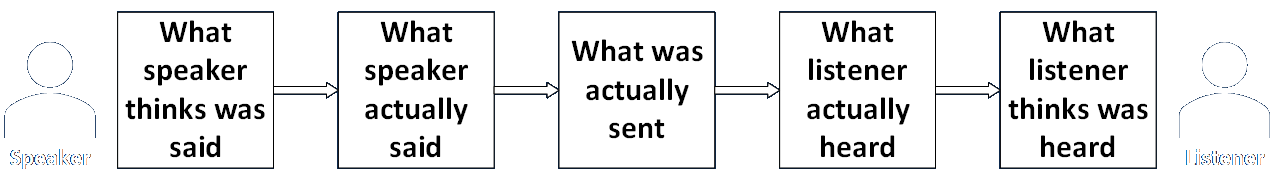
I’ll start by observing that all interfaces involve a form of communication, a basic model of which is shown here.
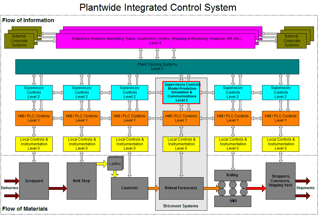
The next diagram shows not only the physical flow of material though a manufacturing process, but also the flow of information between the many different control and information systems that govern and support the entire process. There are quite a few as you can see, and there are even more when you consider that the level 3 and 4 systems are abstract representations of operations that themselves consist of many individual computers and networks, many of which are connected to similar systems in entirely different organizations.
The colored arrows at the bottom indicate the temperature (and sometimes state) of the physical material as it moves through each piece of large industrial equipment (the furnace can be up to 800 feet long), while the unfilled arrows show the flow of information between different instruments and computer systems. Humans interact with many of the systems shown, which constitutes yet another class of interface.
Those communications operate on different types of protocols, on varying electrical connections, with different kinds of verification methods, on very different timings. Some communication channels need to be able to handle many different kinds of messages, each of which may contain multiple pieces of information. The format and meaning of each of those individual values has to be identified, negotiated, implemented, and tested by the engineers who create the systems that pass the messages back and forth.
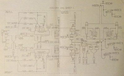
Nuclear power plants may contain on the order of fifty separate fluid systems, and those interface with many different electrical systems and further models for each different type of equipment (valves, pumps, indicators, and so on). The diagram below shows the first of three pages of just one of those fifty thermohydraulic systems. Any link that ends in an incoming or outgoing arrow shows an interface with some other system. Note that this diagram was prepared in the process of creating an operator training simulator for a particular plant. Some of the connections are to other systems contained in their own piping and equipment networks, like this one, while others connect to models of rooms and other containing spaces. Since all of these models (except the core model) ran on one of the CPUs in the same computer system, sharing the same memory space and programmed in the same language, the interfaces between models were a little bit simplified. A little. The engineers still had to agree on, implement, and test the meaning, units, range of values, and memory format of every variable shared between models.
Finally, I discuss many aspects of low-level electronic communications in a series of articles here.