Simulating Human Action

I used the book “Fundamentals of Classical Thermodynamics” by Van Wylen and Sonntag for my thermodynamics classes in college. In the first chapter it discussed the magnitude of relativistic effects compared to the magnitude of the general effects that would be discussed through most of the book. The point was that these effects were so small from an engineering perspective they could be neglected.

A simulation is just another kind of engineering problem where care must be taken to identify elements that will have meaningful effects on the outcome and those that won’t. Adding more and more effects to the simulation, if their magnitudes are continually smaller, yields diminishing returns. The effects become marginally less important.

I spent five years working with a team simulating the logistics of aircraft reliability and maintenance and the team members revisited the effects continuously. There was even a proposal by the customer to include a whole host of additional elements to the simulation, and by a whole host I mean every tangential thing you could think of like the personnel doing the paperwork in the support units, the equipment and service bays needed to perform specialized operations associated with maintenance of certain parts, and more. The base simulation considered about eight major elements but this expansion would have added in the neighborhood of thirty more. It was ambitious, it was interesting, and it was even plausible.

Almost.

The first problem is that the customer didn’t ultimately want to pay for it. The software framework was based on almost fifty years of GPSS spaghetti code that was fairly brittle and difficult to modify. If the whole thing had been reimplemented from scratch using a discrete-event simulation framework like the one I’ve been working on it could have been fairly tractable, and this may have happened over the last couple of years. I would certainly have no trouble doing it with a small team in a reasonable time.

The second problem was that it would have been extremely difficult to get the data to accurately represent the various elements for each situation, since each simulation configuration could involve different locations, equipment and facilities, number and type of personnel, number and type of aircraft, and so on.

I’ve mentioned previously that the accuracy of the elements we did model was limited by our inability to model some of the decisions, usually having to do with scheduling and priority optimizations, that the human managers within the system could make. Imagine now if we were trying to model a system where the range of human decisions is all but unlimited?

Modeling human action in a limited sense, like in the aircraft maintenance simulation, works because the range of actions considered is strictly limited. We also did simulations of people evacuating from buildings and even open spaces like the National Mall in Washington, DC. Those work because actors in the simulation only had a few choices. Go this way or that way down the hall, turn left or right at the T, take this stairway or the next, move to this node or that. The number of possible actions was limited.

People have long tried to model the economic actions of humans and this has met with limited success. While there has been some interesting work done in game theory, simulations that try to model wider range of actions are all but useless. Some economists assert that they are essentially impossible. The problems are twofold. One is that such simulations necessarily limit the number of choices the simulated actors can make when the legitimate range of choices they could make is effectively infinite. This is especially true when considering substitution effects (if the price of apples goes up will any individual agent by fewer, more, none at all, buy peaces instead, or bananas, or strawberries, or tennis rackets, or GI Joe action figures, or carpenter’s squares, or trips to Walla Walla, Washington, or some combination of all of those? Go ahead and list everything. Go ahead… I’ll wait!). The second problem is that even if the modeler could identify every possible choice for every actor it would be impossible to collect and incorporate data to describe them all in a meaningful way. You can try to measure what people have done in the past but this is necessarily incomplete and there is no guarantee they will behave the same way in the future. You can take surveys of people’s stated preferences but it is known that people’s actions rarely if ever reflect what they say they want to do beyond limited circumstances. This is true even if people are trying to be as honest and accurate as possible. It’s just the way people work.

Isaac Asimov’s classic Foundation series of books imagined that future humans had spread across the entire galaxy and that an empire spanning it all was in the process of collapsing. Enter a mathematician name Hari Seldon, discussed but not seen in the original trilogy, since it described events after his passing; his character was a main protagonist in some of the later books. The story arc is based on the idea that Seldon came up with a way to simulate the course of human action on a very large scale. It made for terrific science fiction but lousy math.

In either the second or third book of the original trilogy the organization set up by Seldon to use the simulations intended to guide human history in a way that would minimize the effects of the disintegration of the galactic empire begins to encounter major problems in their attempts to shape events. It turns out that a single individual who is never named but refers to himself as “The Mule,” arises that is able to read minds, and this gives him extraordinary leverage over people and events. He comes out of nowhere and threatens to disrupt everything. Fortunately for the citizens of the galaxy he is eventually neutralized.

Sometimes you just have to accept that there are things you can’t calculate. In simulation terms there isn’t only one Mule. In open-ended situations, everyone is The Mule.

Posted in Simulation | Tagged , | Leave a comment

Model-Predictive Control

Model Predictive Control comes in different forms, but all variations work in roughly the same way. Traditional forms of control act on signals derived from a currently-determined (usually by sensors) state and the difference between that state and the desired state. The current state provides the control signal (or signals) and the desired state is defined by one or more setpoints. Control is effected by acting on the difference between the control signal and the setpoint.

Predictive control algorithms work by modeling the action of the system to some future point in time while incorporating information about what is expected to happen within the system. These future activities can include expected actions of the control system, transformations of elements affected by the system (workpieces or process materials, usually fluids), and scheduled and predicted future events. These methods can work on continuous, discrete, and hybrid process systems.

A continuous process system would be exemplified by a steam-based power plant, an oil refinery, or any other continuous fluid process. Events like process additions, batch operations, and valve movements may be discrete but the overall process would still be continuous. An assembly line, piece inspection process, or vehicular transportation system would be described as discrete. This kind of system must track individual objects and agents as they move through the modeled system and interact with or are acted upon by process elements within that system. Events like arrivals, control actions, and prioritizing and routing decisions can all be considered. Processes in the bulk manufacturing industries (metals, plastics, ceramics) are often hybridized since they include processes where the subject materials are in both liquid and solid states at different times. Moreover, if supporting parts of the process operate on a continuous basis, then they would have to be modeled as continuous processes, also. Examples here would include gas- or oil-fired furnaces and liquid refrigerant systems.

Some reasons to consider future events within a control scheme include:

  • the control process needs to control for a future state that is not measurable in a direct way (i.e., it is not linear or is known to be affected by events yet to occur)
  • the process is speculatively predicting outcomes based on multiple possible outcomes, which may be based on known, scheduled, or randomized but otherwise variable events
  • the process is being optimized based on criteria that cannot be measured directly (e.g., optimizing on cost based on time and resource consumption)

You can see how these items are related.

A special class of systems involves the simulation of properties that cannot be measured, but which can be inferred (calculated) based on information that is available. It may be too fine a linguistic distinction but any system that considers future behavior can be said to me a model. By simulation in this sense, and this is not covered in the Wikipedia article linked at the beginning of this article, I mean a physics-based, first principles determination of conditions that cannot be measured.

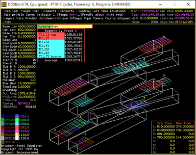
The primary example from my experience is the heating of steel workpieces in reheat furnaces. The goal of a reheat furnace is to control the temperature of a piece of steel so it is ready to be shaped by some kind of rolling (or less often stamping) process. Two requirements for the heating are set: the average temperature of the entire workpiece and the maximum differential temperature of the workpiece. The latter is just the difference between the highest and lowest temperatures known to exist within any regions of the piece. Let’s say we have a goal of 2250 degrees F for a steel ingot. What good does it do us if the outer surface of the piece is 2470 degrees while a section of the interior is only 1500 degrees? Such a situation could cause no end of problems. The grain structure of the material could be very different in different regions and this could cause major structural discontinuities. Having an internal section be so cold could cause the workpiece to deform in undesirable ways in the first rolling operations, or could break the rolling stands outright.

If you’re asking yourself how the internal temperature of different regions of a workpiece can be known then go to the head of the class. While it is possible to embed thermocouples (bimetallic devices used to measure temperature) within a workpiece it is wildly impractical to do so at industrial quantities and rates. We can measure the surface temperature of workpieces with pyrometers (which use infrared radiation readings) but that only tells us what’s happening on surfaces we can see. not only can we not see every surface this surely doesn’t tell us about anything going on below the surface.

Enter the simulation.

We know the initial temperatures of the piece (especially if it’s been sitting outside for any length of time); we know about the material’s thermal conductivity and heat capacity as a function of temperature; we know the piece’s dimensions and density; and we know how much of every region of the piece’s surface is either visible to the furnace environment, or in contact with a hearth, support beam or roller or rack, or adjacent to another workpiece. If we know the temperature of the furnace (and contact points like hearths, beams, rollers, or racks) then we can break the piece down into regions along an internal cross-section and apply calculations that give us the temperature at each region within the piece.

This technique allows the control system not only to calculate values for control variables that cannot be measured, it allows the system to predict a future state of the values at some point in the future based on multiple future events. First, the future event is determined to be the time each workpiece is discharged from the furnace. Since there are almost always multiple pieces in a furnace at any time, the current state is simulated forward in time, considering the movement of the pieces (based on movement rules and opportunities, the current operating pace, scheduled events, and other possible factors) and the operation of the temperature control system of the furnace itself (it assumes the furnace temperature will move toward setpoints at different rates depending on the current rate of fuel and air flow), until each piece has left the furnace (in the simulated future). If the furnace’s zone temperature setpoints and movement operations are expected to cause the workpieces to be discharged at the correct average and differential temperatures, then the zone and movement setpoints aren’t changed. If the discharge results vary from the goal then the system’s setpoints are adjusted. This process is iterative and runs every few seconds.

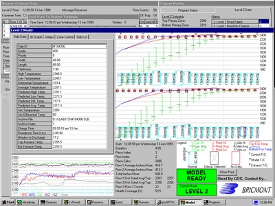
This figure shows a simulation tool I wrote that graphically displays the current and predicted discharge temperature of workpieces in a two-line tunnel furnace (or rolling hearth furnace) with complicated movement rules. A separate caster injects warm workpieces into the charge end of each furnace. The swivel sections rotate to allow pieces to transfer from line B to line A, where they can be discharged to the single, six-stand rolling mill. The lower graphic shows the current temperature at each internal and surface node in the workpiece while the upper graphic shows the predicted discharge temperature at each node. Both depictions show the current location of each workpiece.

This animation (which I wrote) shows how the pieces move through a two-line tunnel furnace that uses shuttle sections instead of sections that swivel. In this case only the current temperatures and locations of the workpieces are shown. You can see how the top an bottom surfaces cool as the discharging piece make their way from the furnace exit to the first mill stand. The surfaces not only lose heat to the atmosphere but also to the jets of water sprayed on to remove surface scale.

Link to full resolution video here.

This figure (which I also wrote) shows how the current and predicted discharge temperatures were displayed in a three-zone, two-column pusher furnace where the first two zones are top- and bottom-fired and the slabs rest on pairs of narrow beams while the third and final zone (to the right) is top-fired only and the slabs rest on a solid hearth.

There are a lot of ways to configure such systems as you can see.

A colleague of mine managed the implementation of a real-time system that would tell the operators of land border ports of entry when to open and close primary inspection booths based on the length of queues of vehicles waiting to be processed, with the goal of ensuring that wait times were never more than a preset duration. The system was based on continually measuring the length of the queue, determining how many vehicles the queue must contain, and assuming that the average processing time and variations in processing time would hold to historical norms. It would start from an initial condition based on the sensors, simulate the inspections of all vehicles waiting in the queue, and determine how long the process was expected to take. We used the standard simulation for design and process improvement analyses; it could be run about once every twenty minutes.

If the process was expected to take more than a specified time then an officer would be dispatched to open another booth so the inspection rate could be increased. If the wait was about the expected time then no changes would be made. If all of the waiting vehicles could be processed in a short enough time then the managers could close a booth and free up an officer for other duties or to go home. This is an example of a discrete process using a form or model predictive control because the process is dealing with discrete entities (or agents) and events.

As it turns out the systems was developed and paid for but never fielded. The customer was not sufficiently confident of the readings provided by the queue length sensors, the practical variability of the inspection times was too great, the reliability of the system was not adequate, and the customer did not want to be bound to the system’s suggestions (in part because the port did not always have enough officers to perform the required inspections). That said, I think we can expect this kind of thing to become more widespread in the future.

Posted in Uncategorized | Leave a comment

“What is a Mutex?”

This was the first question I was asked in an interview sometime around 2006. I didn’t know the answer, which is exceptionally annoying because I’d been using them for years without knowing what they were called. This is a danger of not having read enough of the right materials or of being trained as a mechanical engineer and then as a programmer rather than a pure computer scientist from the get-go. Take your pick.

Mutex is a portmanteau of the words “mutual exclusion.” What this describes in practice is a mechanism for ensuring that multiple processes cannot inappropriately interact with a common resource. This usually means that multiple processes cannot change a common resource at the same time, since doing so may break things in a big way (see the example from the Wikipedia link describing what can happen when two processes are trying to remove adjacent elements from a linked list). Another way this comes up is when a writing process needs to update multiple common elements that describe a consistent state and needs to prevent one or more reading processes from reading the data while the write process is underway. Under some circumstances it’s just fine to allow multiple reading processes to access a shared resource, but the state has to remain consistent.

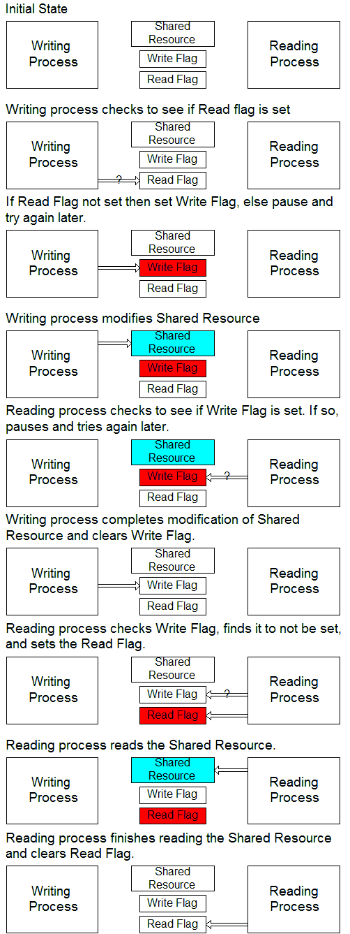
Let’s visualize how this works. We’ll do this in a general way and then describe some specific variations in how this concept can be implemented.

The details of this process can very widely:

  • The “Writing” and “Reading” processes can, in fact, be performing any kind of operation, though this should only be an issue if at least one of the processes is writing (this means modifying the shared resource). What’s really important is that both processes should not be accessing the shared resource at the same time.
  • The flags can be separate items or a single item made to take on different values to reflect its state.
  • The flags can be variables stored in a specified location in memory, files on a local or remote disk, entries in a database table, or any other mechanism. I have used all of these.
  • The different processes that modify and read the data can be threads in the same program, programs on the same machine, programs or threads running on different CPU cores, or processes running on different machines (which would have to be connected by some sort of communication link).

It’s good practice to observe a few rules:

  • A process should access the shared resource for the minimum possible time. Don’t lock the resource, read an item from it or write an item to it, do some stuff, read or write another item, do some more stuff, and so on: write or read and store local copies of everything at once and release the resource.
  • You should be aware of how long processes are supposed to take and implement means of resetting flags left set when things go wrong.

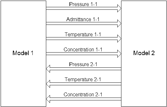
One of my first jobs was writing thermo-hydraulic models for nuclear power plant simulators (oh yeah, I knew there was a reason I was a mechanical engineer first and a software engineer second…) that were implemented on systems that had four CPU cores and a memory space shared by all, so I got an early education in real-time computing. The modelers and utility engineers had to define interfaces that would allow models to exchange information. A simplified version of a model interface is shown below.

These bits of information might be used to model a single fluid flow between two plant systems. Fluid flow is a function of the square root of the pressure difference between two points (that is, if you want twice the flow you have to push four times as hard). The modelers know that the flow will always and only be subcooled liquid water so specifying the temperature also allows each model to calculate the thermal energy moving between systems. The concentration is a normalized number that described the fraction of the mass flow that is something other than water (in a nuclear power plant this might be Boron, a basic kind of radiation, a trace noncondensable gas, or something else). Both models must supply a pressure value to describe what’s happening at their end of the connecting pipe. Both models must supply values for temperature and concentration because the flow might go in either direction, based on which pressure is higher. Finally, only one model provides a value for the admittance, which considers the geometry of the pipe, the position of valves, the viscosity of the water, and the square root function, because that provides a more stable and consistent value.

So why do we care about details like this? Well, models take a finite amount of time to run, and they do things in a certain order. For example, a fluid model will read in the interface values from a number of other models in the simulator. Then it will calculate the flows in every link within its boundaries using a pressure-admittance calculation. Then it will use the flow information to calculate how much energy is carried to each region within the model so new temperatures can be calculated. Then a similar procedure will be used to update the values for concentrations in each internal region. Once that’s all done the model would copy all values that need to be read by other models into dedicated variables used for just that purpose.

Compressing the reading and writing of interface variables into the smallest possible time windows makes it far less likely that model 2 will be trying to read while model 1 is writing the updated values. This would be much more likely if model 1 weren’t copying all of its interface values to a special area of memory in a narrow slice of time rather than simply updating those values after each described series of calculations. If model 2 copied model 1’s interface variables over time then some of the variables (maybe the pressure and admittance) would represent a state from the current time step, while other variables (the temperature and concentration in this example) would reflect the state left over from the previous time step. This would be bad practice because the simulation would be likely to lose its ability to conserve mass and energy across all its models, and would generate increasingly large errors over time.

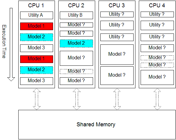
The systems we worked on at Westinghouse didn’t actually use mutexes, I didn’t use them formally until I started writing model-predictive control systems for steel reheat furnaces a couple of years later. The Westinghouse models usually had to rely on being made to run at different times to maintain protection from state corruption. The diagram below describes a simplified version of what was going on. Some utility routines (we called them “handlers”), like the ones used to sense actions by operators pushing buttons, would run as often as sixteen times a second to make sure no physical operator interactions could be missed. Most models of the plant’s electrical and fluid systems ran two or four times per second, while a handful of low-priority models ran only once per second.

Let’s suppose model 1 (shown in red) is set to run in CPU 1 at the rate of twice per second. The diagram shows one second of execution for each CPU. Where should we set up model 2 (possible positions of which are shown in light blue) to run so we know it won’t try to read or write interface variables at the same time as model 1? The diagram shows that models running in the same CPU will never run at the same time (they are all run naively straight through). It also shows that we should try to change the order (and frequency) of executions within each CPU to minimize conflicts.

Given that such simulators modeled up to fifty fluid systems, a dozen-ish electrical systems, and hundreds of I/O points, pumps, valves, bistables, relays, and other components it’s easy to see that there’s only so much that can be done to hand-order the execution of different model codes. The problem is made even more difficult by the fact that the execution time of any model can vary from execution to execution depending on which branches are taken. Therefore, compressing the window of time during which any model or process needs to access its interface variables the more the state integrity of the system will be protected. You can picture that on the diagram above by imagining the reading and writing of interface variables to take up just a small sliver of time at the top and bottom (beginning and end) of each model iteration. The narrower the slivers the less likely there is to be unwanted overlap.

The consequences of losing this integrity might not be that meaningful in the context of a training simulator, but if things get out of sync in an industrial control system, particularly one that controls heavy objects, operates at extreme temperatures, or involves hazardous materials the consequences can be severe. You don’t want that to happen.

The beginning of this article discussed explicit mutexes, access locks that use an explicit change of state to ensure the state integrity of shared resources. The latter part of the article discusses implicit mutexes, which may not even be “a thing” discussed in the formal literature but of which the system engineer must be aware. Some of the considerations described apply to both types.

Posted in Software | Tagged , , | Leave a comment

Course Wrap-up: JavaScript: Understanding the Weird Parts

I finished plowing though Anthony Alicea’s Udemy course, JavaScript: Understanding the Weird Parts, and found it to be quite satisfying. To answer the question left hanging yesterday, yes, the course did describe more details of prototype inheritance, and it did so in a way that confirmed my previous intuitions.

Where the course really paid off for me was when it spent a few lectures exploring the internals of the jQuery framework, with the (somewhat) surprising revelation that it leverages still another framework called Sizzle. That exploration showed how jQuery is constructed in a way that made the application of the course material seem tractable in popular and complex usage situations, and led to an excellent demonstration of using the same layout to build one’s own library or framework using the same techniques. I suspect I will be using just these methods when I get to turning my graph and discrete-event simulation projects into external libraries.

I particularly liked the way the object methods were appended to an object within a closure instead of outside of it, which makes the whole thing sit more cleanly on the page (or in the editor). I’ve found adding the function prototypes after the closure to be a bit unsatisfying.

I’m sure there’s a lot more going on in the JavaScript language that isn’t covered by this course, especially having to do with many of the additions in ES6 and with DOM events more generally, but I was pleased that my previous efforts had already led to a fairly deep understanding of the language. I plan to begin plowing into the React framework next, which I hope will give me more insight into how the event structure works.

Posted in Software | Tagged , , | Leave a comment

JavaScript Inheritance: A Form of Composition

Lectures 53 through 56 of JavaScript: Understanding the Weird Parts discuss more about the creation and manipulation of objects under the hood. I’d seen different aspects of this material previously, which gave me a different take on how to build up objects using prototype inheritance, but these lectures took the ideas apart and put them together in a whole new way.

Let me start by describing what I’d understood previously, and how I did so in terms of OOP formations I’ve seen in previous lives as a Pascal and then C++ programmer for many, many years.

Let’s start by looking at an object I build up using prototypes in the Discrete-Event Simulation project, namely the base entity object that represents items that are moved through the model. I described how I moved all of the member functions to be outside prototypes so the instantiated objects would be smaller here but I don’t think I ever displayed the code, so here it is. The original internal functions are present but commented out so you can see their original form, and the prototype copies of those functions are included below the closure definition, but attached to the closure.

My conception of what’s going on under the hood may not be correct, but I’m visualizing that the JavaScript engine is storing prototypes of each method separately in memory and instantiating objects that include links to the methods instead of complete copies of the methods for each instantiated object. I was thinking of this as being similar to a virtual method table in a more traditional language, where the instantiated object includes memory space for the data members and a single pointer to an entry in the VMT that describes what methods are accessible to that object in that object hierarchy. The setups would not be analogous but the ideas would be similar. The point of the exercise in JavaScript, at least for my purposes, was to reduce the size of the instantiated objects because you don’t want them to carry the burden of huge amounts of code if large numbers of them are going to be created. The data members (properties) have to be unique for each instantiation but the function definitions can be shared.

Various instructions around the web gave me the idea, that prototype inheritance can be used to create different object configurations be defining an initial object with a given set of prototype functions, as I’ve done with EntityPassive, and then add — and remove — prototype functions and members to create the new forms that are desired. This is different than what I’m used to, where object hierarchies can only be defined so the descendant objects are necessarily larger than the parent objects on which they are based. The JavaScript method seems more flexible.

All this said, that was just my conception, I never experimented with actual code to see just how this could work. I envisioned it as being just a hair clunky, but there’s some possibility that it doesn’t work like this at all.

That brings us to the present subject, which is a different description of how those methods work. I can see the similarities to my conception but a) the material in the lectures is very clear and b) the demonstrations show that what is described actually works.

The presenter provided a lot of background concepts to set everything up, then walks through the implementation of the extend function in the Underscore.js library. It uses the ideas of reflection and composition to parse other object definitions to determine what properties they contain (data and function members) and adds them to the object of interest. The parsing process is reflection and the addition process is a form of composition.

Here’s the relevant code from Underscore.js:

Here’s the class example of how this is invoked (see line 36):

In the end I’m thinking that my conception was pretty well on target. The composition-by-addition demonstrated here works the way I envisioned, and objects can as easily be modified by removing elements. That said, defining things this way vs. using prototype definitions as I did above creates objects that have different payloads under the hood. This is something that must be understood by the practitioner. I look forward to seeing what, if anything, the presenter has to say on the subject.

Posted in Software | Tagged , , , , , , | Leave a comment

JavaScript IIFEs

The Udemy course, JavaScript: Understanding the Weird Parts, includes 85 lectures. In lecture 45 I finally encountered something meaningfully new, IIFEs, or Immediately Invoked Function Expressions. This construction is unique to JavaScript in an explicit sense, though there is mention that another language has a similar feature. Their purpose is essentially to manage scope (or namespaces) and this comes up in two different ways.

One involves encapsulating a complex calculation in the global scope to keep it separate from inline code. This involves writing a function as an expression and without a name, and then burying it in parentheses (other syntaxes are possible) to establish the new scope. The encapsulated function may take parameters supplied to the function in their own parenthesized list, and has to return a result, perform an action, or leave some other side-effect in a global variable. The nice part is that within this temporary and protected scope you can declare “local” variables without having to worry about collisions with named variables in other scopes (mostly the global scope).

The other way involves encapsulating the code in an entire file within parentheses, which puts all its code and variable names in a separate scope and namespace. A lot of frameworks are apparently distributed in this form and the contents are accessed by declaring a local (global) variable and setting it to the contents of the external file, so everything in it can be addressed as localVar.anythingintheframework.

This can be done just as easily with a traditional function, at least for inline code at the global level.

Like many things in JavaScript it’ll take me a while to really grok this formation, the need for it, and its implications. I understand why it works the way it does in the context the course is explaining (quite well, I might add) but why it’s needed is a different question. This is just my initial understanding and I’ll have to do more digging around. Not every resource describes things quite the same way at first blush, though obviously they are all getting at the same underlying truth.

Posted in Software | Tagged | Leave a comment

A Better Insight Into Agile and Scrum Roles

I’ve been attending a lot of meetups over the last few months and the one for the Pittsburgh chapter of the IIBA (International Institute of Business Analysts) was special because of the terrific speaker. A gentleman named Rick Clare gave a talk entitled “Debunking Agile Myths” that clarified some things I didn’t have an accurate view of. Here’s a pdf of the slide deck.

Scrum is just a subset of the Agile idea and I’ve always worked in an iterative way while gathering and responding to continuous feedback from the customer. The last company I worked for began some light experimentation with Scrum. The details of that situation gave me a potentially skewed idea of the requirements for the ScrumMaster and Scrum Product Owner roles, and those misapprehensions persisted through all of the training and certification classes and subsequent reading.

Ours was a small development shop with no more than two or maybe three development efforts going on at any one time, and with teams of no more than two to five members, many of whom are part time on any give project. The teams rotated across projects, generally not working on any one for more than three months at a time. The individual who took on the ScrumMaster role was also the head programmer, architect, and tool maven and set direction for pretty much everything that was done within the company. I therefore had the impression that this was a required skillset for ScrumMasters rather than simply being a champion for the Scrum process itself.

As a long time software engineer and architect myself, and as a systems analyst, simulationist, discovery and data collection analyst, and customer liaison I was the natural person to take on the Scrum Product Owner role. Most of the rest of the team were developers and analysts with two to fifteen years of experience, and very few of them were allowed to make decisions about architecture or tools.

As Mr. Clare worked through his discussion of ten Agile myths, most having to do with Scrum as he did not address Kanban, Extreme, or other areas, he gave me a new understanding of the requirements for the Scrum roles. Given that this was a meeting of business analysts he described how business analysis was a key component of performing all or part of each of the three roles. Some members of the development team clearly need to be developers, QA/testers, DBAs, and so on but BAs are clearly intended to serve in this role. The team has to have the requisite knowledge of tools, test and deployment methods, and so on, but this knowledge does not have to reside in the ScrumMaster or Scrum Product Owner; they are supposed to be primarily concerned with the Scrum process itself and the business needs of the organization.

I have been of the opinion that I should not serve as a ScrumMaster because I am not currently a guru in any organization’s end-to-end tool chain and methodology, which now seems like less of a problem. I have also felt that I just haven’t seen the Scrum process up close enough to serve in the role, which seems likely to remain an accurate view.

I have been suggesting that I should serve as a Product Owner because of my previous roles as an analyst, liaison, and architect, and also because I had served in the roles during our brief explorations. Of course, I was also a subject matter expert in POE (Port-of-Entry) operations and simulation within our company so that was reasonable for the situation. Mr. Clare explained that the role is best suited to a senior employee or executive that has a strong understanding of the business needs of the organization. This individual has to be able to interact with the development team, but perhaps knowledge of the business needs is more important than the ability to understand the details of what’s going on inside the development team. That said, one of the most important functions of the Product Owner is grooming the backlog, and I have been discovering, defining, negotiating, and managing requirements, change control and design procedures, and punch lists for most of my career.

This view is supported by an experience I had applying to a company I was introduced to through a friend. I applied for the Product Owner position only to learn, after a polite acknowledgment that my application was impressive but not quite what they were looking for, that the company expected the individual would be someone with previous experience developing SAAS (Software-As-A-Service) frameworks. I’ve certainly worked with numerous tools and frameworks, and even designed some light frameworks, and I’ve definitely worked through full-scale BPR (Business Process Reengineering) engagements and transformations, and I’ve even served as a Project and Program Manager in different contexts, but I had never combined all of those experiences in a single role the way that company was looking for.

I didn’t hear anything new about the Scrum process itself, the steps and ceremonies are pretty straightforward and there’s no part of it you can’t just look up in a book, class materials, or online. It’s all about the meta-process, working with customers, and solving problems efficiently and effectively, and I’ve been doing that for a long time.

So, what to do moving forward? Should I simply target BA positions, for which I am exceptionally well-suited, clearly, or continue to look for a break as a PO in the right situation, on that concentrates on simulation, process analysis, operations research, or some other area of concentration for me, or even a ScrumMaster in an even more rare situation? Time will tell, I guess. I’ll keep working, applying, and learning, and I’ll see where it goes.

Posted in Tools and methods | Tagged , , , | Leave a comment

To Do List Project: Part 10

Right now just plowing ahead with either PHP/MySQL, Bootstrap, or whatever is going to be kind of rote. Make filters, pretty up screens, etc. That would just be practice reps without much hardcore learning. Therefore, once I finish plowing through the remaining videos in the JavaScript: Understanding the Weird Parts course by Anthony Alicea on Udemy I’m going to dive into a course in the React framework, which a) seems rapidly up-and-coming, b) might give me more insight into managing the connection between the front and back ends, c) give me some ideas for managing the UI in the To Do app from a different viewpoint, and d) allows me to follow the recommendation of several people I’ve talked to. I can see where it’s heading using raw JS and PHP but it’ll be more interesting to see how a newer framework updates the concepts.

For better or worse I’ve chosen Modern React with Redux by Stephen Grider, also on Udemy. I feel I’ve had good luck so far!

Posted in Software | Tagged , , | Leave a comment

A Simple Discrete-Event Simulation: Part 89

Direct link for mobile devices.

I was walking a few miles in the nice weather this evening when two possible solutions popped into my head for the DisplayGroup drag problem I had in the simulation app (where the pointer arrow from the edge of the DisplayGroup object to the edge of the DisplayItem object does not get drawn if the intersection tests generate false negatives). As long as the idea was fresh I figured I’d go ahead and check it out. It turned out that I already do one of things that occurred to me so that quickly proved to be a dead end. The other idea appears to solve the problem for all the cases I’ve tested.

The problem I found with the method I originally implemented solved for the intersection of two lines using the slope and y-intercept formula. The problem with that is that some values for the y-intercept can be quite high which can lead to rounding errors at the intersection point. If I write formulas for the lines in terms of one of the endpoints of each line then the formulas get slightly more complex but the accuracy of calculating the intersection point should increase.

The point-slope formula for a line is:

    yp = y1 + m12 * (xp – x1)

where:

    xp, yp = location of arbitrary point on line
    m12 = slope of line, (y2 – y1) / (x2 – x1)
    x1, y1 = location of line endpoint 1
    x2, y2 = location of line endpoint 2

Substituting for the yp we look to solve for xp for the intersection of lines 12 and 34

    y1 + m12 * (xp – x1) = y3 + m34 * (xp – x3)

    y1 + m12 * xp – m12 * x1 = y3 + m34 * xp – m34 * x3

    m12 * xp – m34 * xp = y3 – y1 + m12 * x1 – m34 * x3

    xp * (m12 – m34) = y3 – y1 + m12 * x1 – m34 * x3

    xp = (y3 – y1 + m12 * x1 – m34 * x3) / (m12 – m34)

Once you have the x-coordinate then you get the y-coordinate by reinvoking the first formula. The code has to do some testing for special cases involving vertical and horizontal lines as shown in the new intersection function here:

Click or tap on any of the non-path objects to make the associated DisplayGroup object visible, then drag that object around the screen with the mouse or by touch. The pointer appears to render smoothly in all cases.

Posted in Software | Tagged , , , , , | Leave a comment

To Do List Project: Part 9

I spent way too many hours not getting something to work that should be simple. I’m sure that I’m missing something obvious but I need to throw in the towel for today and get a post up.

The problem is this: I’m redoing all the screens to use responsive formatting with Bootstrap and the features I’ve used so far on the Update To Do item page have all worked fine. I went to replace the standard navigation menu, defined in the NavMenu.php file, with a collapsible Bootstrap-style version. I started by copying in a simple example of such a menu, edited to reflect the navigation options from this application, only to find that it didn’t display the way I expected it to. All that would display is a very small box with no detail, which represented the button that should appear at the right end of the top menu. It neither displayed at the right end of the top menu bar nor expanded when clicked.

Some inspection and reading clarified how the reference to the Bootstrap CSS file needs to be added in the header and the references to the jQuery and Bootstrap JavaScript files need to be included at the bottom of the page body. That made the expand and collapse operations work but the button was still not in the correct location and none of the formatting was correct. It was as if the file was picking up the Bootstrap JavaScript but none of the Bootstrap CSS.

I tried building a simple HTML page that includes essentially nothing but the menu code, and that worked fine. I then changed the name of the test file to use a PHP extension, but which used no PHP code (the idea was to reference the NavMenu.php file using an include statement as I have been), and that also worked — when I ran it directly from disk. I then ran it from a server in CloudNine and it didn’t work, which is maddening.

It occurred to me that there may be a version mismatch between the jQuery and Bootstrap (CSS and JavaScript) files but why would that only show up when running from a server?

By the way, I also tried a number of combinations and permutations on the original Update To Do item page and found that the CSS must be getting picked up because all of the other bootstrap features work as expected. It’s just the collapsible menu that’s giving me fits. Like I said before, I’m probably missing something mindless, and I’m definitely beating the related mechanisms into my programming “muscle” memory, but for right now I’m stumped.

Here’s the code for the standalone PHP file that works when run from disk but not when run from a server.

Here’s how the sample page should look when the screen is wide enough to show the menu items:

Here’s how the sample page should look when the screen is collapsed so that only the button shows. I can confirm that the button can be clicked to show the correct vertical menu.

Here’s how the sample page looks when it doesn’t work. Clicking on the button shows or hides the vertical menu items but the menu items never show horizontally.

It seems to me that the Bootstrap JavaScript is working and the Bootstrap CSS is not working. If you have any ideas, feel free to give me a shout.

Posted in Software | Tagged , , , | Leave a comment