
Model Predictive Control comes in different forms, but all variations work in roughly the same way. Traditional forms of control act on signals derived from a currently-determined (usually by sensors) state and the difference between that state and the desired state. The current state provides the control signal (or signals) and the desired state is defined by one or more setpoints. Control is effected by acting on the difference between the control signal and the setpoint.
Predictive control algorithms work by modeling the action of the system to some future point in time while incorporating information about what is expected to happen within the system. These future activities can include expected actions of the control system, transformations of elements affected by the system (workpieces or process materials, usually fluids), and scheduled and predicted future events. These methods can work on continuous, discrete, and hybrid process systems.
A continuous process system would be exemplified by a steam-based power plant, an oil refinery, or any other continuous fluid process. Events like process additions, batch operations, and valve movements may be discrete but the overall process would still be continuous. An assembly line, piece inspection process, or vehicular transportation system would be described as discrete. This kind of system must track individual objects and agents as they move through the modeled system and interact with or are acted upon by process elements within that system. Events like arrivals, control actions, and prioritizing and routing decisions can all be considered. Processes in the bulk manufacturing industries (metals, plastics, ceramics) are often hybridized since they include processes where the subject materials are in both liquid and solid states at different times. Moreover, if supporting parts of the process operate on a continuous basis, then they would have to be modeled as continuous processes, also. Examples here would include gas- or oil-fired furnaces and liquid refrigerant systems.
Some reasons to consider future events within a control scheme include:
- the control process needs to control for a future state that is not measurable in a direct way (i.e., it is not linear or is known to be affected by events yet to occur)
- the process is speculatively predicting outcomes based on multiple possible outcomes, which may be based on known, scheduled, or randomized but otherwise variable events
- the process is being optimized based on criteria that cannot be measured directly (e.g., optimizing on cost based on time and resource consumption)
You can see how these items are related.
A special class of systems involves the simulation of properties that cannot be measured, but which can be inferred (calculated) based on information that is available. It may be too fine a linguistic distinction but any system that considers future behavior can be said to me a model. By simulation in this sense, and this is not covered in the Wikipedia article linked at the beginning of this article, I mean a physics-based, first principles determination of conditions that cannot be measured.
The primary example from my experience is the heating of steel workpieces in reheat furnaces. The goal of a reheat furnace is to control the temperature of a piece of steel so it is ready to be shaped by some kind of rolling (or less often stamping) process. Two requirements for the heating are set: the average temperature of the entire workpiece and the maximum differential temperature of the workpiece. The latter is just the difference between the highest and lowest temperatures known to exist within any regions of the piece. Let’s say we have a goal of 2250 degrees F for a steel ingot. What good does it do us if the outer surface of the piece is 2470 degrees while a section of the interior is only 1500 degrees? Such a situation could cause no end of problems. The grain structure of the material could be very different in different regions and this could cause major structural discontinuities. Having an internal section be so cold could cause the workpiece to deform in undesirable ways in the first rolling operations, or could break the rolling stands outright.
If you’re asking yourself how the internal temperature of different regions of a workpiece can be known then go to the head of the class. While it is possible to embed thermocouples (bimetallic devices used to measure temperature) within a workpiece it is wildly impractical to do so at industrial quantities and rates. We can measure the surface temperature of workpieces with pyrometers (which use infrared radiation readings) but that only tells us what’s happening on surfaces we can see. not only can we not see every surface this surely doesn’t tell us about anything going on below the surface.
Enter the simulation.
We know the initial temperatures of the piece (especially if it’s been sitting outside for any length of time); we know about the material’s thermal conductivity and heat capacity as a function of temperature; we know the piece’s dimensions and density; and we know how much of every region of the piece’s surface is either visible to the furnace environment, or in contact with a hearth, support beam or roller or rack, or adjacent to another workpiece. If we know the temperature of the furnace (and contact points like hearths, beams, rollers, or racks) then we can break the piece down into regions along an internal cross-section and apply calculations that give us the temperature at each region within the piece.
This technique allows the control system not only to calculate values for control variables that cannot be measured, it allows the system to predict a future state of the values at some point in the future based on multiple future events. First, the future event is determined to be the time each workpiece is discharged from the furnace. Since there are almost always multiple pieces in a furnace at any time, the current state is simulated forward in time, considering the movement of the pieces (based on movement rules and opportunities, the current operating pace, scheduled events, and other possible factors) and the operation of the temperature control system of the furnace itself (it assumes the furnace temperature will move toward setpoints at different rates depending on the current rate of fuel and air flow), until each piece has left the furnace (in the simulated future). If the furnace’s zone temperature setpoints and movement operations are expected to cause the workpieces to be discharged at the correct average and differential temperatures, then the zone and movement setpoints aren’t changed. If the discharge results vary from the goal then the system’s setpoints are adjusted. This process is iterative and runs every few seconds.
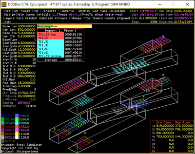
This figure shows a simulation tool I wrote that graphically displays the current and predicted discharge temperature of workpieces in a two-line tunnel furnace (or rolling hearth furnace) with complicated movement rules. A separate caster injects warm workpieces into the charge end of each furnace. The swivel sections rotate to allow pieces to transfer from line B to line A, where they can be discharged to the single, six-stand rolling mill. The lower graphic shows the current temperature at each internal and surface node in the workpiece while the upper graphic shows the predicted discharge temperature at each node. Both depictions show the current location of each workpiece.
This animation (which I wrote) shows how the pieces move through a two-line tunnel furnace that uses shuttle sections instead of sections that swivel. In this case only the current temperatures and locations of the workpieces are shown. You can see how the top an bottom surfaces cool as the discharging piece make their way from the furnace exit to the first mill stand. The surfaces not only lose heat to the atmosphere but also to the jets of water sprayed on to remove surface scale.
Link to full resolution video here.
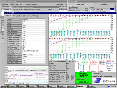
This figure (which I also wrote) shows how the current and predicted discharge temperatures were displayed in a three-zone, two-column pusher furnace where the first two zones are top- and bottom-fired and the slabs rest on pairs of narrow beams while the third and final zone (to the right) is top-fired only and the slabs rest on a solid hearth.
There are a lot of ways to configure such systems as you can see.
A colleague of mine managed the implementation of a real-time system that would tell the operators of land border ports of entry when to open and close primary inspection booths based on the length of queues of vehicles waiting to be processed, with the goal of ensuring that wait times were never more than a preset duration. The system was based on continually measuring the length of the queue, determining how many vehicles the queue must contain, and assuming that the average processing time and variations in processing time would hold to historical norms. It would start from an initial condition based on the sensors, simulate the inspections of all vehicles waiting in the queue, and determine how long the process was expected to take. We used the standard simulation for design and process improvement analyses; it could be run about once every twenty minutes.
If the process was expected to take more than a specified time then an officer would be dispatched to open another booth so the inspection rate could be increased. If the wait was about the expected time then no changes would be made. If all of the waiting vehicles could be processed in a short enough time then the managers could close a booth and free up an officer for other duties or to go home. This is an example of a discrete process using a form or model predictive control because the process is dealing with discrete entities (or agents) and events.
As it turns out the systems was developed and paid for but never fielded. The customer was not sufficiently confident of the readings provided by the queue length sensors, the practical variability of the inspection times was too great, the reliability of the system was not adequate, and the customer did not want to be bound to the system’s suggestions (in part because the port did not always have enough officers to perform the required inspections). That said, I think we can expect this kind of thing to become more widespread in the future.