A Simple Discrete-Event Simulation: Part 43

Today I went through and cleaned up each of the component definitions in the process of implementing the ability to rerun the simulation without having to refresh the browser page. Beyond just neatening up the code for each component I added a reset function which resets all of its state properties but leaves the established configuration properties (definition, layout, and linking) in place. The reset function then just has to cycle through each component in the listOfComponents array and call the reset function for each. I can then just reset the discrete-event timing mechanisms and a handful of other global control/state variables (which should ultimately be given their own namespace and separate file). The global timing mechanisms and control variables should be reset before the list of components, since resetting the components sometimes refers to the global values (mostly the global simulation clock).

Here’s the snippet that gets executed when the Reset button is clicked, along with one example of a reset method in a component object. As a side note I found it interesting that the parameters to the JavaScript closure constructors are always available, like that’s just another way of declaring an internal member property. I’m sure I’ve made use of this effect previously, but the awareness just became conscious.

I made sure the components were all drawn once the system was initialized and when it is reset, so they’re visible before the simulation starts running. I’m thinking I’ll want to split the drawing of paths up so that the lines are drawn with all of the other objects and then the nodes and entities are drawn separately and later, so nodes always sit on top of both components and entities always sit on top of components and nodes.

I also noticed that certain aspects of the Queue component behave a bit differently if there is an assumed minimum traversal time, as would be the case for a physical queue, vs. a zero traversal time as would be the case for a logical or information-only queue. I’ll sort that out in a future post, at which I’ll make the same modifications (if and as needed) for the Path and Process components, which maintain internal queue mechanisms of their own. I have thought that processes represented by Process components must always involve a non-zero processing time but I also recognize that some processes only involve making instantaneous decisions. That may call for a new kind of primitive component type.

Another thing I realized as I was reviewing and cleaning things up today was that my original concept of handling discrete event queue items was that they would be created once, with a call to feq.newItem, and then recycled back into the future events queue continuously using the advance function. However, in a lot of cases components will “lose” the future events queue item when they reach a state where they must wait to be activated by an external event. In this case they cannot rely on being able to recycle and existing future events queue item because the handle to it may have been lost. This situation is made even more confusing by the fact that there can be multiple discrete-event timing items active at any one time within a component (i.e., there can be numerous pucks), so keeping track of them might be problematic.

The advance function as it was written (and still survives in the current incarnation of the Arrivals component because it effectively operates independently of any other component). I’m thinking I need to expand the concept of the advance function so it figures out whether to use an existing discrete-event timing item or whether it needs to create a new one. It shouldn’t be too hard to create a handle for the necessary item; the Component code “knows” whether a component is going to be left alone to “die” (i.e., not be recycled through the future events queue and be automatically garbage collected).

The feqCurrent item is always the most recent item pulled from the future events queue. If it’s going to be recycled back into the future events queue we can use the existing advance function. If a new event needs to be created we might implement an “advanceNew” function to create a new item, or we can simply hijack the existing item. I’m going to have to draw out the state values as things proceed so I am perfectly clear on what’s needed. I could simply create new objects for every item I’m going to put into the queue whether it’s recycled or new, but relying on automatic garbage collection to keep up with objects that would be created at such a great rate (this is the most common thing that happens in a discrete-event simulation model, after all) seems extremely wasteful.

It also occurs to me that when defining forward links of paths to downstream components that the process of defining an accompanying upstream link can be automated when the need for it is detected. This would have to be the case when linking to downstream components that are not guaranteed to be able to receive new entities (i.e., they must clear before sending an open signal back upstream to the sending component). This also says that the definition for whether the linking path is exclusive or not is actually defined by the nature of the downstream component being linked to, so the linking path should take on this characteristic automatically, and define the required upstream link, based on whether the linked-to downstream component is exclusive.

It may be that the minimum definitions should be generated by the designer and that upstream links should be defined automatically as part of the post-definition and verification process. A verification process should be implemented to test that all required elements are defined and that the required components and connections are in place to support every defined routing. The direction of paths should be considered as part of this as well.

If that all seems less than clear I feel your pain, but these very insights were the main purpose of today’s explorations. I’m going to work on implementing the cleanup of the linking and exclusivity process tomorrow and the new vs. advance issue in the post after that.

Including thoughts from previous posts and some other items that need to get done, here’s the current to do list. It’s going to keep me plenty busy as you can see. I’m likely to take breaks from this project to work on other things, but since this is something I’ve always wanted to do on my own so I’ll always come back to it. I’m also sure that I’ll continue to add to this list. The main thing is that I’ve gotten the project to a takeoff point where it’s fun to work on and produces highly visible results.

  • Standardize linking and exclusivity process
  • Resolve and standardize new vs. advance issue
  • Rework drawing of Path components so correct elements are always on top
  • Rework the Queue mechanism to flexibly handle finite-traversal time and zero-traversal time configurations
  • Revisit distribution logic to make sure it’s cycling the way it should be.
  • Learn JavaScript’s prototype object pattern and re-implement everything in that in place of the closure pattern I’ve been using; I’ll want to bite that bullet before this thing goes much farther
  • Expand Path component representation so it can incorporate multiple line segments
  • Add ability to sense reaching tail end of FIFO queue based on stopping to wait on a Path component; collect statistics accordingly (possibly add wait flag to entities so they can test against the next entity in line)
  • Look into creating a zero-duration, zero-queue decision component
  • Create standardized routing mechanism (to components of different types) based on process logic (vs. distribution logic to multiple components of the same type)
  • Implement mechanism to identify combinations of related components into groups (e.g., a group of tollbooths represent a single toll plaza)
  • Gather and report system-, component-, and group-level statistics
  • Add ability to stream large volumes of output information which can be post-processed and quantified via a parsing mechanism
  • Streamline the process of defining the endpoints of Path components (i.e., attach standard nodes to other components and connect to those automatically, which will greatly save on the number of x,y locations the designer must specify manually)
  • Add an edit mode that allows designers to change component properties interactively (ultimately including being able to drag them)
  • Use the new, completely external mechanism for displaying component data
  • Describe how abstract representation can be used to represent detailed layouts and interactions; include ability to flag or alarm situations which would cause conflicts in the real world that would not necessarily be captured in a model unless specifically tested for
  • Add the ability to graph outputs as part of reporting
  • Add scrolling, animated graphs to illustrate progress as simulations run
  • Include ability for users to call up component and entity status by written or graphical display interactively while runs are in progress
  • Create streamlined graphical representations of all component types; create data display for Path components
  • Add ability to display entities inside relevant non-path components
  • Abstract the current x,y locations of all elements and scale them to the screen so the user can zoom in and out
  • Add ability for users to interactively change things during runs
  • Add Monte Carlo mechanisms to various timing and routing events (beyond what’s already been demonstrated)
  • Allow designer to build Monte Carlo and other distributions from acquired data using standardized tools
  • Add ability to perform multiple runs and statistically quantify generated outputs
  • Make simulation display update at regular intervals of simulated time rather than intervals defined by individual events; also make this “speed” scalable
  • Include ability to add arbitrary graphic elements to models (labels, keys, tables, etc.)
  • Include ability to display an underlay “below” the model display (e.g., a floor plan of a modeled process)
  • Allow user to turn off display and run model in “fire-and-forget” mode where it generates results without wasting time redrawing graphics.
  • Allow user to selectively turn different display elements on and off
  • Add ability to assign open/close schedules for components and groups
  • Add ability to introduce multiple types of entities in model with different processing rules for routing and timing
  • Add ability to combine multiple queues into a single, logical unit
  • Add ability to adapt stand base components to represent varied and specialized things (this applies mostly to Process components)
  • Add ability to save and restore model definitions (in files/XML and in databases, requires PHP/MySql, Node.js or other back end capability)
  • Add ability to represent more abstract processes:
    • Reintroduce wait..until mechanism that uses the current events queue
    • Include pools of resources that are needed by different processes
    • Implement non-FIFO queues or collections that receive and forward entities based on arbitrary (user-defined) criteria
    • Include ability to accept events that happen according to fixed schedules rather than random ones (e.g., to match observed data)
    • Include the ability to change representation of entities and components to represent state changes (by color, shape, labels, flags, etc.)
    • Support input and editing of modular packages of information used to define and drive models
    • Add ability to represent BPM processes using standard BPMN notation
  • Really complex stuff
    • Develop more complex, arbitrary node-and-link representation of model, which brings up worlds of complications on its own!
    • Polish related sections of code and break them into modules which can be included on a modular basis
    • Make modules and examples distributable for use by a wider community
      • Write documentation for modules as needed
      • Share on GitHub
      • Create dedicated project page on my website
      • Update and enhance my custom Graph component as well as the simulation framework
  • Re-implement this system in a more appropriate language like C++ or at least Java
Posted in Simulation | Tagged , | Leave a comment

A Simple Discrete-Event Simulation: Part 42

Today I replumbed the layout of components to include a single entry, a single queue, and two processes that each feed the single exit. This required the following modifications:

  • The Queue component had to support multiple outgoing paths.
  • The Queue component had to be able to alternate sending entities forward along the various outgoing paths, subject to the next (Process) component being open and available. In practice what this means is that when an entity reaches the front of the queue it increments the counter for the most recently-used path. It then checks to see if that path is open and if not, it continues to increment (possibly wrapping around to the first path) and test until an opening is found or all paths have been tested. This ensures that entities are forwarded uniformly to the connected downstream processes, subject to variations in the time it takes to process the entities in the downstream process components. This mechanism is appropriate when a queue is feeding multiple components of the same type, which should always be the case. If a component supporting multiple output paths is meant to direct entities to downstream components of differing types then a routing mechanism should be used that is driven by the logic of the process. We saw the mechanics of this idea yesterday as entities were routed from the Arrival component to the different Entry components based on assigned percentages.
  • The Queue component now incorporates the concept of a minimum transit time. When an entity enters a Queue it initiates a discrete-event timing event, and when that event is picked off the future events queue we know the entity is available to be forwarded. The Queue component attempts to forward the entity as described above and, if cannot do so, it waits until one of the downstream processes calls back to pull an entity from the Queue.
  • The logic for determining whether downstream components are open or upstream components have entities available to pull may have to consider the status of the path that connects the downstream or upstream component to the current component. Whether or not this complication has to be considered depends on whether the path has been marked as exclusive. Non-exclusive paths are connected to downstream entities that are defined to always be able to receive entities (e.g., the Queue and Exit components, and technically the Entry components and non-exclusive Path components–so far). Components can only forward entities along exclusive paths if the downstream Path component is empty and the downstream connected (Process) component is open. Components retrieving entities from upstream through a connected path (which should only be possible along an exclusive Path component) have to request the previousComponent.previousComponent‘s forwardEntity method to pull an entity forward.
  • I tweaked the timing of the various components a little bit and added two more 30-minute time intervals to the end of the run, during which no new arrivals are generated. I did this to ensure that the simulation would always clear.

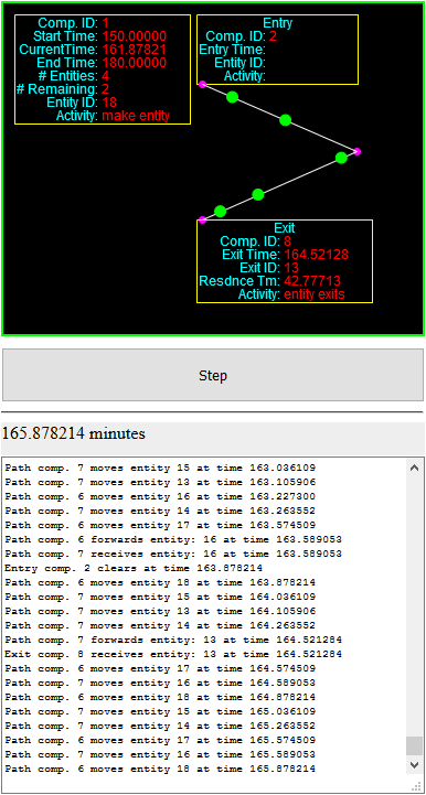
Here’s the model as it has been updated and configured.

I’ll skip the listings for the modified components today, since they need to be cleaned up a bit, but I will include the updated code for initializing everything.

This took longer than I expected today so I’m also going to forego implementing the capability to reset without refreshing the browser page.

Tomorrow I’ll try to get that done and see if I can’t streamline and automate a few mechanisms and definitions. I’ll also make the display smaller by cutting some of the display information out of the component visuals, now that we know things are working. Things are getting a bit unwieldy here and need to be cleaned up!

Posted in Simulation | Tagged , | Leave a comment

A Simple Discrete-Event Simulation: Part 41

Today I took a step back to slightly simpler version of the simulation that uses the original version of the Path components (the ones that have the nodes built into them and act like standalone components). I took two steps forward, however, in that I added new complexity to the framework by providing the ability to include multiple entry points and the ability to either step through the simulation or run it so it steps through the simulation automatically. I also added the ability to pause the simulation when it’s running automatically.

Up to now I’ve assumed that components can only be linked together in one line; each component was linked to exactly one subsequent and/or one previous component. I started to allow for more arbitrary constructions when I developed separate nodes that could be linked to multiple incoming or outgoing paths. We aren’t using independent nodes here so we have to recreate that capability using the components we do have. We can start by allowing the Arrivals component to be linked to multiple Entry components. You can see this in the demo; there is one Arrivals component and two Entry components. Each Entry component is linked to a separate Path component and each Path component is then linked to the single Exit component. It’s a pretty simple setup, but it includes everything needed to illustrate the principle.

The code for the Arrivals component includes a few changes. We’ve eliminated the single value for nextComponent and replaced it with an array of values called entryList. This allows the Arrivals component to be linked to as many Entry components as desired.

We’ve also added an additional input parameter to the constructor or initial call, in the form of an entryDistributionArray. This array should have as many primary members as there are time slices in the model (we’ve been going with twelve time slices of thirty time units each). Each member of the array should itself be an array with as many members as there are linked Entry components. This information is used in the forwardEntity method in the following way. The values in the secondary dimension of the array represent the cumulative chance that any given entity arrives at that Entry component, ranging from 0.0 to 1.0 and always increasing. We initialize each array to have values of 0.7 and 1.0, which means that 70 percent of the entities will be forwarded to the first Entry component while the other 30% will be forwarded to the second Entry component. If we had assigned five possible Entry components we might specify a secondary array of [0.4,0.45,0.6,0.9,1.0], which means that Entry components one through five would be expected to receive 40, 5, 15, 30, and 10 percent of the generated entries, respectively. The actual selection is based on the result of a call to Math.random(), which generates a value between 0.0 (inclusive) and 1.0 (not inclusive).

That’s really all there is to it. At this point none of the other components had to be changed. That said, I did add a counter to each Entry component to keep track of the number of arriving entities routed to each. Since I assigned values of 0.7 and 1.0 for each of the 12 time slices we would expect roughly two-thirds of the entities to arrive through the first (left hand) entry components. Since the results are generated randomly and the browser (I tested this only on Firefox and Safari) doesn’t reset the random number seeds when I refresh the page to rerun the model, the exact distribution varies a little bit between runs.

Here’s the code that initializes everything, including the division of arrivals by Entry component.

We’ve assigned the diversion percentages for the arrivals (from the Arrivals component to the various Entry components) by time slice but there may not be a need to add that much complexity. If the division by entry point doesn’t change over time then a single set of values could be used just as easily. I’ve worked with some very complex models that made this assumption.

Tomorrow I’ll continue adding complexity by adding the ability to specify multiple destinations to at least one other component type.

Finally, I will also see if I can’t allow the user to reinitialize and rerun the simulation without having to refresh the whole browser page.

Posted in Simulation | Tagged , | Leave a comment

A Simple Discrete-Event Simulation: Part 40

Today I modified the framework to define Node components separately from Path components. This allows us to have any number of paths going into or out of any node so that any arbitrary network can be defined. In the code’s current state components that are not nodes or paths can hand entities off to other components that also aren’t nodes or paths, or to nodes. Nodes can hand entities off to paths or to components that aren’t nodes or paths. Paths can on receive entities from nodes and hand entities off to nodes.

This is actually a little bit awkward, and we are on a bridge between two versions of what this kind of discrete-event simulation model can be. One version is more abstract and considers only how entities move from component to component. It might not be very interesting visually, but it would be very fast and would get the job done as far as performing the desired analysis. The other version is more detailed and would effectively do away with all components that are not nodes or paths. In this version the process activities would take place at nodes and queues would form wherever nodes backed up behind processes. That can make it a bit trickier to figure out when an entity entered a given queue but that’s just a technicality.

The more detailed version is much more complex to write and debug and takes more memory and execution time (potentially by a lot) but if way more visually interesting. Observers can see exactly what’s going on inside the model as it runs (or as a run is replayed). For the time being I’m going to back up and finish building out the more abstract version. To give it some visual interest, however, I will retain the visual paths between components so users can get more of a feel for where entities are being sent in a simulation. I might back the representation of the nodes and paths to the earlier version where I defined paths with nodes included on each end, and ensure that I never include more than one path between components (if possible).

There’s a lot that can be done with a more abstract version of this tool and I have an interesting in getting something more interesting running and usable. I plan to do the more interesting and detailed version going forward, and that will involve finding detailed solutions to the problems of entities competing to pass through intersections, as has been discussed over the last couple of days. I think it’ll be helpful to build that kind of framework and play around with it rather than try to whiteboard everything up front where it’s hard to follow what might be going on.

In the meantime here is the code for the new Node component. Notice that there are currently no discrete-event handling mechanisms in this version. When a component (path or otherwise) hands an entity off to the node it immediately gets forwarded to the next component. This may not be enough in the long run, but it works well enough in my test case so it is sufficient for now. The node can be connected to one or more paths or a single non-path component either coming in or going out, so the node figures out the kind of forwarding or receiving to do be checking against the number of incoming or outgoing paths that are linked to the node. Also, when the end of a path is assigned to a node the assignment causes some relevant values to be assigned within the path component.

Here’s the updated code for the Path components. It is almost untouched from its previous version.

Here’s the new code that initializes everything.

It doesn’t look any different than it did before, and it still works, so that’s always good!

Posted in Simulation | Tagged , | Leave a comment

A Simple Discrete-Event Simulation: Part 39

Today I continue thinking about the details of how entities interact with each other at intersections (and in general).

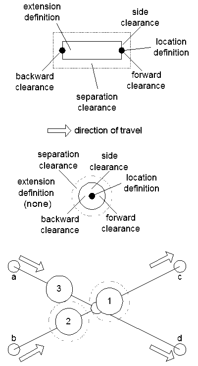
The upper two sections of the figure below describe various dimensions that must be considered. The top section describes a rectangular entity, which might represent a vehicle. The next section down describes a circular entity of the type we’ve been working with. We’ll begin by describing what all the dimensions represent.

  • location definition (T): This is the primary definition of where an entity is on a path (the T is for traversal). It is defined in terms of the distance traversed along a path. The x- and y-locations in space are derived from that. For a rectangular entity the location is defined from the front center of the rectangle. For a circular entity the location is defined from the center, though in theory it could be redefined to represent the forward edge of the circle. That might be better from a consistency standpoint. The location definition is the only definition that defines the location of the entity in space; all of the other values are relative to the location definition or other points within the entity.
  • extension definition (E): This defines a point at or near the back end of the entity. The back end of a rectangular entity would also have to move along the path, though calculating its x- and y-locations would be more complicated. The distance between the location definition and extension definition would not change, so placing it on a path would have to consider junctions and angles between two or more paths.
  • separation clearance (C): This is the distance that must separate entities in any direction.
  • forward clearance (F): If the location definition is not at the leading edge of the entity, this defines the distance to the leading edge.
  • backward clearance (B): This is defined as the distance to the back end of the entity from the location definition or the extension definition. For a circular entity this is equal to the radius of the circle (or it could be the diameter). For a rectangular entity this is the distance to the back end from the extension definition. This distance might be set to zero for a car, as an approximation, but it might have a meaningful value for a box truck where the rear end extends well beyond the rear axle which serves as its pivot point and extension definition.
  • side clearance (S): It is assumed for the time being that all entities will be symmetrical across the direction of travel. This distance is from the center line of the entity to either side of the entity. For a circular entity this distance is equal to the entity’s radius.

I’m also going to define a distance (N), which is the distance toward the intersection node, along one or more path segments (without branches). The length of the current path will be referred to as (L).

Looking at the lower section of the image we can analyze how the described measurements affect the movements of entities across node junctions.

  • Following an entity in general: No following entity’s forward-most location (defined by T+F) can move beyond a traverse distance defined by T-E-B-C.
  • Approaching an intersection at which a different entity will arrive first or is currently passing through: The approaching entity must stop (that is, the leading edge defined by L+F cannot go beyond this point) at a distance from the intersection defined by N-S-C if the angle between converging paths is greater than 45 degrees. If the angle is less than 45 degrees then this distance is defined by N-E-B-C. For circular entities N-S-C should be the same as N-E-B-C. Think of this like cars merging into traffic. A car turning in from a side road (angle > 45 degrees) needs clearance of a car width plus a buffer. A car merging in at a shallower angle ( < 45 degrees) would need an entire car length plus a buffer.

This line of thought suggests that it might be a good idea to have each node store the distance along all subsequent paths to the next intersection or activity node.

The implementation has to be worked out in detail, but it seems like we may be able to accomplish what we want using a fairly small set of generalized rules, which is always desirable.

Posted in Simulation | Tagged | Leave a comment

A Simple Discrete-Event Simulation: Part 38

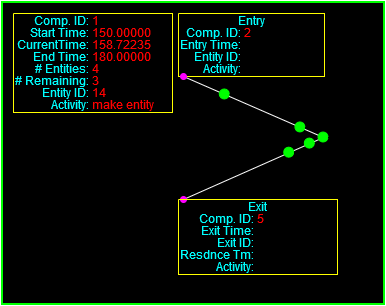
Today I set up two Path components so they are linked in series as shown here.

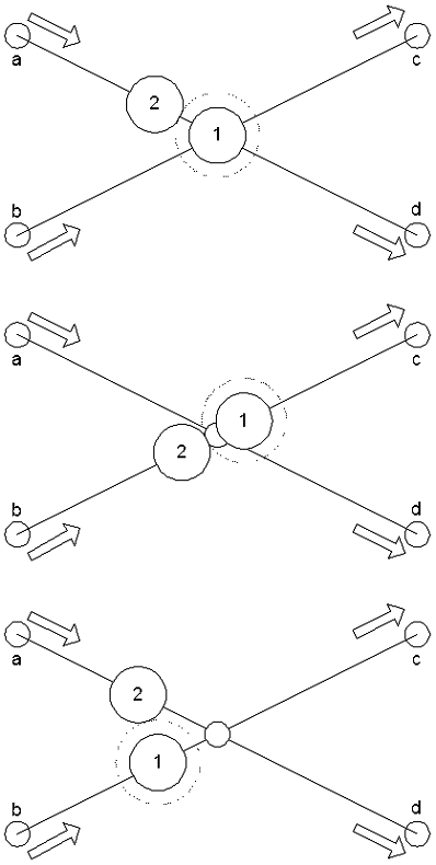
The hand-off worked well enough but it’s clear that more thought needs to be given to the details as entities move from one path to another across the connecting node. I created the following diagrams to help me think things through.

The existing positions of each entity are defined by the center of the circle that represents it. There also has to be a certain amount of clearance between each entity, which is shown by the dotted line around the lead entity. When an entity is sitting on an intersection node then the situation is pretty straightforward, as illustrated in the top figure. The endTraverse value is set to define how far the following entity can go along its path. That value would be set by the traversal distance of entity 1 along path c or d, minus the radius of the lead entity, minus the required clearance between entities, minus the radius of the trailing entity. If that distance is longer than a short path that terminates at the connecting node, then the value is decremented by the length of the short path and the process is completed for the next path back.

The middle figure shows the situation where the lead entity starts to pull away from the intersection. In this case the code needs a way to tell any paths that end at the intersection how much space is left. Here I’m thinking that the information should be reported to the node (which will soon become an independent component separate from each Path component) so that any path which connects to it can easily access the information. That way we don’t have to worry about trying to propagate the information back to a whole list of paths that might terminate at a node.

Then I started thinking about what happens when entities are approaching a node from multiple paths, as illustrated in the bottom figure. After thinking about it for a while it seemed clear to me that each path has to report the arrival time of the next entity at the terminating node (the intersection), and then the node will give permission to the path whose entity will arrive soonest. So, entity 1 will have permission to approach the end of its path because its effective endTraverse value will be zero (of whatever value is set by an entity that hasn’t gotten far enough out of the way down paths c or d. Entity 2, approaching on path A, will have its endTraverse value set to a default that will allow sufficient clearance for entities to pass through the intersection node, which for this demo will be the radius of the moving entity plus the required clearance plus the radius of the waiting entity, or 5 + 2 + 5.

If one of the paths approaching the intersection node is shorter than the clearance space (the endTraverse value), then that will have to be taken into account as well. This indicates that when handling the movement on its leading entity will have to trace its predicted movements all the way to the next node that has multiple terminations, or at least across a reasonable distance.

One final complication arises here, and that is if the speed along one path is higher than the speed along a different path by enough that the entity from the faster path always take precedence. This could happen if there are numerous entities densely packed along the faster path. On the other hand, this situation would not happen if there were sufficient gaps between entities on the faster path. I’m going to keep this idea in the back of my head for now but we’ll remember it if it comes up somewhere down the line. There are many ways to resolve situations like this.

Posted in Simulation | Tagged | Leave a comment

A Simple Discrete-Event Simulation: Part 37

Today I finished putting together a basic Path component. It mostly works like a queue but it has “physical” dimensions that take time for the entities to traverse. It also draws the path, its endpoints, and any entities in their proper positions.

The Path is component three in the demo. It’ll take a lot of clicks to get through it.

(Click on the “Step” button to advance through the model, refresh the page to run it again.)

Here’s the code for the Path component.

Here’s how the Path component is instantiated and initialized. In the longer run we want a very generalizable element that can connect anything to anything, including to other Paths. In practice we’ll define nodes independently and then link the paths to pairs of nodes so that completely arbitrary networks can be defined. For now the endpoints are defined directly within the Path component. The Path has an implied direction, and elements can only move along it one way. That said, the path can go in any direction on the screen and the code will handle it naturally.

If entities are moving along the path they are going at the assigned speed; there is no mechanism for accelerating and decelerating. That can be added later if we want. Entities are assumed to have a radius of five and require a clearance of two. For the time being the units of measure are in screen pixels. Later we’ll have to add in the ability to scale the elements, which will add another layer of complexity. If an element cannot move the full distance it “wants” to, because it has to wait for an element in front of it to move out of the way, it pauses for a definable interval (I think one time unit in the demo) and then tries to move again. This is akin to simulating the reaction time of people or vehicles edging forward in queues. They don’t all move in lockstep, they take a certain amount of time to react to the space that opens up in front of them.

I had to add another layer of complexity to the discrete event handling mechanism because we are treating the moving entities as being entirely passive. If an entity within a component needs to be moved according to independent logic that uses the discrete event handling mechanism, then the item that goes into the future events queue has to carry information about the component and the specific entity within the component. Looking at the relevant calls:

Here’s the updated definition of the newItem method in the FutureEventsQueue object. The only change is that it passes the newly added fourth parameter, the one pointing to the internal entity, to the new FutureEventItem call.

Here’s the updated code for the FutureEventItem object. All it does is store the extra entity reference.

Here’s the working result of all this, in the activate method of the Path component:

JavaScript is bizarre in many ways but one of the nice things about it is that if you choose not to include parameters at the end of the list for function calls, and the relevant variables or parameters are never accessed, then everything goes on working as before. That means that all the other uses of this mechanism that don’t use the extra entity parameter will continue to work without modification. We have to keep track of this kind of thing carefully. JavaScript won’t let you shoot yourself in the foot in the same way that C or C++ will, but it’ll give you a whole new set of creative ways to do it.

There are some other things that bear further description but I’ll get to those shortly.

I want to observe that I do most of my editing in Notepad++ but I occasionally use WebStorm to help me find certain classes of errors I introduce. I typically do this when the debugger in Firefox refuses to display the code, which means it had trouble parsing something, and I can’t find the error quickly. I may then go through the code to follow some of WebStorm’s suggestions about style, through not all of them. I’ve turned off flipping if-else statements and eliminating curly brackets in one-line loops and if statements, for example.

I do not use WebStorm for interactive debugging because it doesn’t have access to the DOM. That’s only accessible to the debugger built into each browser.

Posted in Simulation | Tagged , | Leave a comment

A Simple Discrete-Event Simulation: Part 36

We’ve had most of the components in place to build meaningful discrete-event simulations for a while, but it can be hard to follow what’s going on without knowing exactly what you’re looking at. To make that easier the next increment of work will involve displaying the position of the entities as they move through the system. So far we’ve assumed that entities move instantaneously from place to place, and in that scenario it’s tough to show motion in any case. We’ll proceed by changing our assumption to say that movements between and through components take a finite amount of time. This would be the case for physical entities moving in the real world, like passengers moving through a border crossing or parts and workers in the process of maintaining aircraft, but it would also be the case for abstract entities like documents and decision data moving through a business process system. Those items might move quickly through the electronic parts of the process but the time it takes to do so would never be zero.

In order to model these effects we’re going to add Path elements to our collection of components. We’ll start by using single Path components as connectors between the existing components (except between the Arrival and Entry components), but we’ll ultimately allow them to be linked together in series and also be integrated into Queue and Process components.

A single Path component has a number of characteristics including start and end locations (which also implies a direction), a (non-zero) length, and a speed at which the entities move. It may have other characteristics based on the nature of the physical path being represented. If the path represents a conveyor then all of the entities might move at the same speed. If the path represents a downward-sloping channel holding a single row of spheres, the spheres may roll based on gravity and friction until they reach the queue, at which point they all advance in unison each time a sphere is pulled from the head of the queue. If the path represents a group of people walking or vehicles moving then they will move under their own power and maintain a minimum clearance between them. When people or vehicles exit a queue it will take a certain amount of time for each trailing one to move forward into the empty space. All of this logic has to be built into whatever path mechanism is constructed.

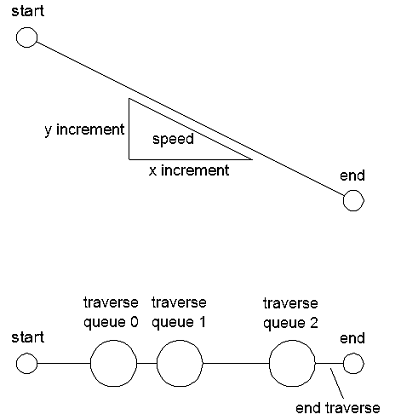
The goal is to make the simulation visually interesting, so I’m going to model the entities as being self-propelled, requiring a minimum clearance, and requiring a delay when moving forward from a stop. The figure below will aid description of the details.

The upper diagram shows a start and end location along with a speed and an x and y component of speed. The lower diagram shows a path containing numerous entities, each of which has a diameter and a required clearance. Each path is modeled as a queue which has to store not only the entities but also the distance traversed by each entity. The latter information helps the path component keep track of where entities are and when and how far they’re allowed to move. The component also tracks what I call an end traverse, which represents the amount of distance available at the end of the path, beyond the center of the entity which is farthest along the path. Since the paths will start out as stand-alone connectors it will be assumed that the lead entity can always move to the end of the path freely. However, if this path is connected to a subsequent one, an entity near the beginning of the next path could prevent the lead entity on the present path from moving forward. In that case, the assumption would be made that the angle between paths would be shallow enough that it could be treated as a straight line. This saves us from having to consider side clearances as entities navigate acute bends. Finally, the entities move along the path in fixed time increments. That is, when their movement event is picked off the head of the future events queue, they will get to move as far as they can at the relevant speed during the allotted time increment, unless they are blocked by an entity ahead of them or they reach the end of the path segment. In the latter cases a new event is generated for the appropriate time and placed back into the future events queue. If the event involves reaching the end of a path segment it may or may not be handed off to the next segment or component as part of the event.

One other consideration in this case is whether to maintain our current assumption that the moving entities are entirely passive and that all of the active logic is embedded in the components (including Path components). For the time being we’ll maintain this assumption but let me provide a brief description of why it might be reconsidered.

The foregoing description considers the low-level mechanics of movement within individual components, but movements can also be considered at a higher or macro level in a system. So far we’ve just been building up capabilities incrementally so they can be used to represent a linear system. In a more general and interesting simulation there will be multiple paths and there may be a need to calculate the most efficient path to take when different options are available. In that case a search for the least-cost path (where cost is measured in time so it considers process and wait times as well as the time it takes to move) would have to be made whenever multiple routing options exist. The question then becomes whether to implement that search from the “point of view” or the entity or from the “point of view” of the multiple-choice element (which could itself be the intersection of multiple paths or a Queue or Process component in its own right). It really doesn’t matter, and in fact if I were to continue developing this capability without adding the detailed path elements that will make things look more interesting, the next complication to add would be a routing capability. It would figure out where entities would be sent next.

There are two considerations for choosing paths. One is dictated by the logic of the process itself. Depending on the result of process A, an entity could be directed to process B or C. The other consideration for choosing paths is when there are multiple routes to process B or C, once the destination has been determined. If movements are to be purely logical or instantaneous, then the problem of choosing among multiple routes to B or C never comes up.

Here is a general introduction to the subject of path searching as it comes up in this sort of work. Note that the animations included on the page depict grid networks while a couple of the static diagrams show networks of arbitrary paths. I like to refer to the arbitrary path networks as node-and-spoke networks, and that is what I’m constructing here. However, once we have this mechanism built it isn’t a very large jump to grid-based networks. I’ve worked with discrete-event simulations that use both methods.

Posted in Simulation | Tagged , | Leave a comment

A Simple Discrete-Event Simulation: Part 35

Today I finished mods to the DisplayGroup object that allows it to be set up to hide itself a set amount of time after one or more displayed variables change.

We begin with the code that now includes the requisite timing mechanisms. The turnOn method makes the display visible when it is invoked following a change in a displayed value. The turnOff method sets the visibility back to false unless a more recent timer has been started. The setVisibility method allows the visibility to be initialized to false (the default is true).

Here is the code used to initialize a display object in timing mode. This setup makes use of the fact that the updateValue methods for the individual display items can detect whether the values they point to have changed. Note that we can choose which variables can drive visibility changes when they are modified.

Finally, here’s how the updates are called in the main event loop.

Posted in Simulation | Tagged , | Leave a comment

A Simple Discrete-Event Simulation: Part 34

The exercise of writing out requirements and mulling them over yielded the desired insights about how to proceed. Today I’ll describe the external display mechanism, which blindly redraws all of the desired values with every global redraw event and in a manner entirely external to the simulation element.

Here’s the code for the individual display items. The addition here is the updateValue method, which takes the new input value as a parameter. Remembering that JavaScript lets you do some interesting things–while also being highly annoying and cumbersome–we see that the method is capable of handling inputs that are functions. If the input parameter is not a function then the parameter is assumed to be a value which can be assigned directly. If the input parameter is a function (that itself has no parameters, we can expand that capability later), then the method obtains the value returned by the function. Naturally this only works if the function passed as a parameter returns a usable value. This method works for simple functions but does not appear to work if you pass in a method call to an object. That is apparently too many layers of indirection. I have it as a note to explore this further.

The other thing the update does is check to see if the new value is different than the last value. If it is the method returns a value of true (as opposed to a default of false). This capability isn’t important for today’s work but will be for tomorrow’s.

Next up is a reworking of the DisplayGroup object. Since the mechanism must be completely external to any simulation element I went ahead and moved the definition of many of the parameters back to the function/constructor call itself (the define method is left in place for now). I also made the addValue method capable of accepting functions as arguments, with the same limitations described above. I also modified the object so that an empty string can be passed in for the label value, in which case the values will be drawn starting on the first line instead of the second.

Here is the streamlined code for the Queue component, from yesterday.

Here is how a queue component and all of the display mechanisms are instantiated.

Finally, the requisite calls to update and draw the values are made for every screen refresh. In theory these calls can be added to a global array like the components are, which would allow them to also be invoked in a loop.

As described previously, much of this overhead is due to the fact that JavaScript enforces passing simple data types by value, which means we have to go out of our way to provide updates. Beyond that we have to define everything about the external display mechanisms before using them.

Tomorrow I’ll expand these definitions to support display groups that are visible only for a limited time when triggered by a change in the displayed values.

Posted in Simulation | Tagged | Leave a comment