
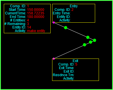
Today I set up two Path components so they are linked in series as shown here.
The hand-off worked well enough but it’s clear that more thought needs to be given to the details as entities move from one path to another across the connecting node. I created the following diagrams to help me think things through.
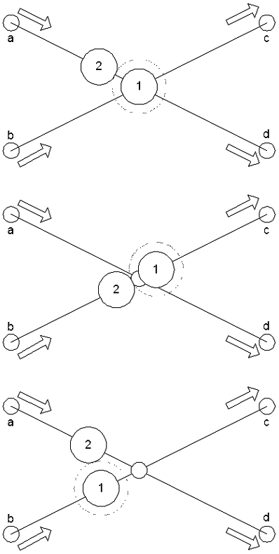
The existing positions of each entity are defined by the center of the circle that represents it. There also has to be a certain amount of clearance between each entity, which is shown by the dotted line around the lead entity. When an entity is sitting on an intersection node then the situation is pretty straightforward, as illustrated in the top figure. The endTraverse value is set to define how far the following entity can go along its path. That value would be set by the traversal distance of entity 1 along path c or d, minus the radius of the lead entity, minus the required clearance between entities, minus the radius of the trailing entity. If that distance is longer than a short path that terminates at the connecting node, then the value is decremented by the length of the short path and the process is completed for the next path back.
The middle figure shows the situation where the lead entity starts to pull away from the intersection. In this case the code needs a way to tell any paths that end at the intersection how much space is left. Here I’m thinking that the information should be reported to the node (which will soon become an independent component separate from each Path component) so that any path which connects to it can easily access the information. That way we don’t have to worry about trying to propagate the information back to a whole list of paths that might terminate at a node.
Then I started thinking about what happens when entities are approaching a node from multiple paths, as illustrated in the bottom figure. After thinking about it for a while it seemed clear to me that each path has to report the arrival time of the next entity at the terminating node (the intersection), and then the node will give permission to the path whose entity will arrive soonest. So, entity 1 will have permission to approach the end of its path because its effective endTraverse value will be zero (of whatever value is set by an entity that hasn’t gotten far enough out of the way down paths c or d. Entity 2, approaching on path A, will have its endTraverse value set to a default that will allow sufficient clearance for entities to pass through the intersection node, which for this demo will be the radius of the moving entity plus the required clearance plus the radius of the waiting entity, or 5 + 2 + 5.
If one of the paths approaching the intersection node is shorter than the clearance space (the endTraverse value), then that will have to be taken into account as well. This indicates that when handling the movement on its leading entity will have to trace its predicted movements all the way to the next node that has multiple terminations, or at least across a reasonable distance.
One final complication arises here, and that is if the speed along one path is higher than the speed along a different path by enough that the entity from the faster path always take precedence. This could happen if there are numerous entities densely packed along the faster path. On the other hand, this situation would not happen if there were sufficient gaps between entities on the faster path. I’m going to keep this idea in the back of my head for now but we’ll remember it if it comes up somewhere down the line. There are many ways to resolve situations like this.