
We’ve had most of the components in place to build meaningful discrete-event simulations for a while, but it can be hard to follow what’s going on without knowing exactly what you’re looking at. To make that easier the next increment of work will involve displaying the position of the entities as they move through the system. So far we’ve assumed that entities move instantaneously from place to place, and in that scenario it’s tough to show motion in any case. We’ll proceed by changing our assumption to say that movements between and through components take a finite amount of time. This would be the case for physical entities moving in the real world, like passengers moving through a border crossing or parts and workers in the process of maintaining aircraft, but it would also be the case for abstract entities like documents and decision data moving through a business process system. Those items might move quickly through the electronic parts of the process but the time it takes to do so would never be zero.
In order to model these effects we’re going to add Path elements to our collection of components. We’ll start by using single Path components as connectors between the existing components (except between the Arrival and Entry components), but we’ll ultimately allow them to be linked together in series and also be integrated into Queue and Process components.
A single Path component has a number of characteristics including start and end locations (which also implies a direction), a (non-zero) length, and a speed at which the entities move. It may have other characteristics based on the nature of the physical path being represented. If the path represents a conveyor then all of the entities might move at the same speed. If the path represents a downward-sloping channel holding a single row of spheres, the spheres may roll based on gravity and friction until they reach the queue, at which point they all advance in unison each time a sphere is pulled from the head of the queue. If the path represents a group of people walking or vehicles moving then they will move under their own power and maintain a minimum clearance between them. When people or vehicles exit a queue it will take a certain amount of time for each trailing one to move forward into the empty space. All of this logic has to be built into whatever path mechanism is constructed.
The goal is to make the simulation visually interesting, so I’m going to model the entities as being self-propelled, requiring a minimum clearance, and requiring a delay when moving forward from a stop. The figure below will aid description of the details.
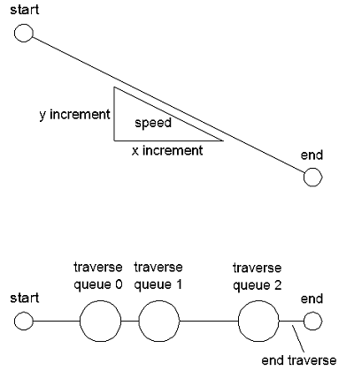
The upper diagram shows a start and end location along with a speed and an x and y component of speed. The lower diagram shows a path containing numerous entities, each of which has a diameter and a required clearance. Each path is modeled as a queue which has to store not only the entities but also the distance traversed by each entity. The latter information helps the path component keep track of where entities are and when and how far they’re allowed to move. The component also tracks what I call an end traverse, which represents the amount of distance available at the end of the path, beyond the center of the entity which is farthest along the path. Since the paths will start out as stand-alone connectors it will be assumed that the lead entity can always move to the end of the path freely. However, if this path is connected to a subsequent one, an entity near the beginning of the next path could prevent the lead entity on the present path from moving forward. In that case, the assumption would be made that the angle between paths would be shallow enough that it could be treated as a straight line. This saves us from having to consider side clearances as entities navigate acute bends. Finally, the entities move along the path in fixed time increments. That is, when their movement event is picked off the head of the future events queue, they will get to move as far as they can at the relevant speed during the allotted time increment, unless they are blocked by an entity ahead of them or they reach the end of the path segment. In the latter cases a new event is generated for the appropriate time and placed back into the future events queue. If the event involves reaching the end of a path segment it may or may not be handed off to the next segment or component as part of the event.
One other consideration in this case is whether to maintain our current assumption that the moving entities are entirely passive and that all of the active logic is embedded in the components (including Path components). For the time being we’ll maintain this assumption but let me provide a brief description of why it might be reconsidered.
The foregoing description considers the low-level mechanics of movement within individual components, but movements can also be considered at a higher or macro level in a system. So far we’ve just been building up capabilities incrementally so they can be used to represent a linear system. In a more general and interesting simulation there will be multiple paths and there may be a need to calculate the most efficient path to take when different options are available. In that case a search for the least-cost path (where cost is measured in time so it considers process and wait times as well as the time it takes to move) would have to be made whenever multiple routing options exist. The question then becomes whether to implement that search from the “point of view” or the entity or from the “point of view” of the multiple-choice element (which could itself be the intersection of multiple paths or a Queue or Process component in its own right). It really doesn’t matter, and in fact if I were to continue developing this capability without adding the detailed path elements that will make things look more interesting, the next complication to add would be a routing capability. It would figure out where entities would be sent next.
There are two considerations for choosing paths. One is dictated by the logic of the process itself. Depending on the result of process A, an entity could be directed to process B or C. The other consideration for choosing paths is when there are multiple routes to process B or C, once the destination has been determined. If movements are to be purely logical or instantaneous, then the problem of choosing among multiple routes to B or C never comes up.
Here is a general introduction to the subject of path searching as it comes up in this sort of work. Note that the animations included on the page depict grid networks while a couple of the static diagrams show networks of arbitrary paths. I like to refer to the arbitrary path networks as node-and-spoke networks, and that is what I’m constructing here. However, once we have this mechanism built it isn’t a very large jump to grid-based networks. I’ve worked with discrete-event simulations that use both methods.