
Today I connected the display of the DisplayGroup objects to the component selection event. That is, if you click on a component it brings up that component’s DisplayGroup object. This process involves several steps.
First, the location on the canvas has to be sensed, and that has been discussed previously. However, I neglected to test the selection functionality when the scene had been dragged to a new location. That was corrected by subtracting the factors globalBaseX and globalBaseY from the actual click location in the same manner that DisplayElement x- and y-locations are modified.
Here’s the updated event handling code, which also shows the new way that mouse click events are handled per yesterday’s discussion.
|
1 2 3 4 5 6 7 8 9 10 11 12 13 14 15 16 17 18 19 20 21 22 23 24 25 26 27 28 29 30 31 32 33 34 35 36 37 38 39 40 41 42 43 44 45 46 47 48 49 50 51 52 53 54 55 56 57 58 59 60 61 62 63 64 65 66 67 68 69 70 71 72 73 74 75 76 77 78 79 80 81 82 83 84 85 86 87 88 89 90 91 92 93 94 95 96 97 98 99 100 101 102 103 104 105 106 107 108 109 110 111 112 113 114 115 116 117 118 119 120 121 122 123 124 125 126 127 128 129 130 131 132 133 134 135 136 137 138 139 140 141 142 143 144 145 146 147 148 149 150 151 152 153 154 155 156 157 158 159 160 161 162 163 164 165 166 167 168 169 170 171 172 173 174 175 176 177 178 179 180 181 182 183 184 185 186 187 |
///////////////////mouse click events var componentSelectionIndex; ///////////////////mouse drag events var dragFlag = false; var startDragX; var startDragY; var dragBaseX; var dragBaseY; var dragLastX; var dragLastY; var totalDragDistance; var mouseTimeStamp = 0; //start drag canvas.addEventListener("mousedown", function(event) { startDrag(event); }); function startDrag(e) { mouseTimeStamp = Date.now(); startDragX = globalBaseX; startDragY = globalBaseY; dragBaseX = e.clientX; dragBaseY = e.clientY; dragLastX = dragBaseX; dragLastY = dragBaseY; dragFlag = true; totalDragDistance = 0; } //end drag canvas.addEventListener("mouseup", function(event) { var endTime = Date.now(); if (((endTime - mouseTimeStamp) < 300) && (totalDragDistance <= 3)) { //treat as a click event componentSelectionIndex = selectComponent(dragLastX+globalBaseX, dragLastY+globalBaseY); } endDrag(event); }); function endDrag(e) { dragFlag = false; } //move while dragging canvas.addEventListener("mousemove", function(event) { doDrag(event); }); function doDrag(e) { if (dragFlag) { var currentX = e.clientX; var currentY = e.clientY; var incrementX = currentX - dragLastX; var incrementY = currentY - dragLastY; if (incrementX > 0) { panLeft(incrementX) } else if (incrementX < 0) { panRight(-incrementX) } if (incrementY > 0) { panUp(incrementY); } else if (incrementY < 0) { panDown(-incrementY); } dragLastX = currentX; dragLastY = currentY; //eat the event if (e.stopPropagation) { e.stopPropagation(); } else { e.cancelBubble = true; } } } //mouse leaves canvas canvas.addEventListener("mouseleave", function(event) { leaveDrag(event); }); function leaveDrag(e) { if (dragFlag) { globalBaseX = startDragX; globalBaseY = startDragY; if (!running) { drawModel(); } dragFlag = false; } } ///////////////////touch drag events, for now only supports first touch point //var dragFlag = false; //var startDragX; //var startDragY; //var dragBaseX; //var dragBaseY; //var dragLastX; //var dragLastY; //var totalDragDistance; var touchTimeStamp = 0; //start drag canvas.addEventListener("touchstart", function(event) { startDragT(event); }); function startDragT(e) { touchTimeStamp = Date.now(); startDragX = globalBaseX; startDragY = globalBaseY; e.preventDefault(); var touches = e.changedTouches; dragBaseX = touches[0].pageX; dragBaseY = touches[0].pageY; dragLastX = dragBaseX; dragLastY = dragBaseY; dragFlag = true; totalDragDistance = 0; } //end drag canvas.addEventListener("touchend", function(event) { endDragT(event); }); function endDragT(e) { var endTime = Date.now(); if (((endTime - touchTimeStamp) < 300) && (totalDragDistance <= 3)) { //treat as a click event componentSelectionIndex = selectComponent(dragLastX+globalBaseX, dragLastY+globalBaseY); } //also process end drag event e.preventDefault(); dragFlag = false; } //move while dragging canvas.addEventListener("touchmove", function(event) { doDragT(event); }); function doDragT(e) { if (dragFlag) { e.preventDefault(); var touches = e.changedTouches; var currentX = touches[0].pageX; //change to clientX var currentY = touches[0].pageY; //change to clientY var incrementX = currentX - dragLastX; var incrementY = currentY - dragLastY; //accumulate drag distance totalDragDistance += Math.abs(incrementX) + Math.abs(incrementX); if (totalDragDistance > 3) { if (incrementX > 0) { panLeft(incrementX) } else if (incrementX < 0) { panRight(-incrementX) } if (incrementY > 0) { panUp(incrementY); } else if (incrementY < 0) { panDown(-incrementY); } dragLastX = currentX; dragLastY = currentY; } } } //touch leaves appropriate area (control works beyond canvas) canvas.addEventListener("touchcancel", function(event) { leaveDragT(event); }); function leaveDragT(e) { e.preventDefault(); if (dragFlag) { globalBaseX = startDragX; globalBaseY = startDragY; if (!running) { drawModel(); } dragFlag = false; } } |
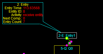
We have to go back to defining the location and properties of each component’s DisplayGroup object, as in this example, which is the only one so far defined. It’s the last line here:
|
1 2 3 4 5 6 7 |
var routingTable = [[1.0],[1.0],[1.0]]; var entry1 = new EntryComponent(routingTable); entry1.setRoutingMethod(3); //1 single connection, 2 distribution logic, 3 model logic entry1.setComponentName("Entry1"); tempGraphic = new DisplayElement(entry1, 210, 5, 68, 20); entry1.defineDataGroup(2.0, 20, -100, 69, globalNeutralColor, globalValueColor, globalLabelColor); |
Drawing the DisplayGroup object is now more complicated, since I’ve chosen to include a pointer from the DisplayGroup’s frame to the edge of the DisplayElement’s frame. The pointer is drawn along the line between the centers of the two frames.
|
1 2 3 4 5 6 7 8 9 10 11 12 13 14 15 16 17 18 19 20 21 22 23 24 25 26 27 28 29 30 31 32 33 34 35 36 37 38 39 40 41 42 43 44 45 46 47 48 49 50 51 52 53 54 55 56 57 58 59 60 61 62 63 64 65 66 67 68 69 70 71 72 73 74 75 76 77 78 79 80 81 82 83 84 85 86 87 88 89 90 91 92 93 94 95 96 97 98 99 100 101 102 103 104 105 106 107 108 109 110 111 112 113 114 115 116 117 118 119 120 121 122 123 124 125 126 127 128 129 130 131 132 133 134 135 136 137 138 139 140 141 142 143 144 145 146 147 148 149 150 151 152 153 154 155 156 157 158 159 160 161 162 163 164 165 166 167 168 169 170 171 172 173 174 175 176 177 178 179 180 181 182 183 184 185 186 187 188 189 190 191 192 193 194 195 196 197 198 199 200 201 202 203 204 205 206 207 208 209 210 211 212 213 214 215 |
function DisplayGroup1(parent) { ... this.drawBasic = function() { this.height = (this.valueCount * 12) + this.labelHeight + 3; this.width = this.maxLabelWidth + this.valueWidth + 8; globalCTX.strokeStyle = this.borderColor; globalCTX.beginPath(); var x1 = this.xLocation-globalBaseX+0.5; //boundaries of dataGroup object var y1 = this.yLocation-globalBaseY+0.5; var x2 = this.xLocation+this.width-globalBaseX+0.5; var y2 = this.yLocation+this.height-globalBaseY+0.5; var cx = (x1 + x2) * 0.5; //center of dataGroup object var cy = (y1 + y2) * 0.5; var px1 = this.parent.graphic.x1-globalBaseX; //boundaries of displayElement object var py1 = this.parent.graphic.y1-globalBaseY; var px2 = this.parent.graphic.x2-globalBaseX; var py2 = this.parent.graphic.y2-globalBaseY; var pcx = (px1 + px2) * 0.5; //center of displayElement object var pcy = (py1 + py2) * 0.5; var drawPointer = true; var test; var ix; var iy; test = intersection(cx,cy,pcx,pcy,px1,py1,px2,py1); if (test !== false) { ix = test.x; iy = test.y; } else { test = intersection(cx,cy,pcx,pcy,px2,py1,px2,py2); if (test !== false) { ix = test.x; iy = test.y; } else { test = intersection(cx,cy,pcx,pcy,px2,py2,px1,py2); if (test !== false) { ix = test.x; iy = test.y; } else { test = intersection(cx,cy,pcx,pcy,px1,py2,px1,py1); if (test !== false) { ix = test.x; iy = test.y; } else { drawPointer = false; } } } } globalCTX.fillStyle = globalBackgroundColor; globalCTX.fillRect(x1,y1,this.width,this.height); globalCTX.moveTo(x1,y1); globalCTX.lineTo(x2,y1); globalCTX.lineTo(x2,y2); globalCTX.lineTo(x1,y2); globalCTX.lineTo(x1,y1); globalCTX.stroke(); var alpha; var ax1; var ay1; var ax2; var ay2; var baseWid = 12; var temp; if (pcx != cx) { var m1 = (pcy - cy) / (pcx - cx); alpha = Math.atan(m1) + Math.PI * 0.5; temp = baseWid * Math.cos(alpha); ax1 = cx - temp; ax2 = cx + temp; temp = baseWid * Math.sin(alpha); ay1 = cy - temp; ay2 = cy + temp; } else { ay1 = cy; ay2 = cy; if (pcy >= pcx) { ax1 = cx - baseWid; ax2 = cx + baseWid; } else { ax1 = cx + baseWid; ax2 = cx - baseWid; } } /* globalCTX.strokeStyle = "#FF8800"; globalCTX.beginPath(); globalCTX.moveTo(ax1,ay1-4); globalCTX.lineTo(ax1,ay1+4); globalCTX.moveTo(ax1-4,ay1); globalCTX.lineTo(ax1+4,ay1); globalCTX.stroke(); globalCTX.strokeStyle = "#0088FF"; globalCTX.beginPath(); globalCTX.moveTo(ax2,ay2-4); globalCTX.lineTo(ax2,ay2+4); globalCTX.moveTo(ax2-4,ay2); globalCTX.lineTo(ax2+4,ay2); globalCTX.stroke(); */ var ix1; var iy1; test = intersection(ax1,ay1,ix,iy,x1,y1,x2,y1); if (test !== false) { ix1 = test.x; iy1 = test.y; } else { test = intersection(ax1,ay1,ix,iy,x2,y1,x2,y2); if (test !== false) { ix1 = test.x; iy1 = test.y; } else { test = intersection(ax1,ay1,ix,iy,x2,y2,x1,y2); if (test !== false) { ix1 = test.x; iy1 = test.y; } else { test = intersection(ax1,ay1,ix,iy,x1,y2,x1,y1); if (test !== false) { ix1 = test.x; iy1 = test.y; } else { drawPointer = false; //alert("this should not happen 2"); } } } } var ix2; var iy2; test = intersection(ax2,ay2,ix,iy,x1,y1,x2,y1); if (test !== false) { ix2 = test.x; iy2 = test.y; } else { test = intersection(ax2,ay2,ix,iy,x2,y1,x2,y2); if (test !== false) { ix2 = test.x; iy2 = test.y; } else { test = intersection(ax2,ay2,ix,iy,x2,y2,x1,y2); if (test !== false) { ix2 = test.x; iy2 = test.y; } else { test = intersection(ax2,ay2,ix,iy,x1,y2,x1,y1); if (test !== false) { ix2 = test.x; iy2 = test.y; } else { drawPointer = false; //alert("this should not happen 3"); } } } } /* globalCTX.strokeStyle = "#FF00FF"; globalCTX.beginPath(); globalCTX.moveTo(cx,cy); globalCTX.lineTo(pcx,pcy); globalCTX.stroke(); globalCTX.beginPath(); globalCTX.moveTo(ax1,ay1); globalCTX.lineTo(ix,iy); globalCTX.stroke(); globalCTX.beginPath(); globalCTX.moveTo(ax2,ay2); globalCTX.lineTo(ix,iy); globalCTX.stroke(); */ if (drawPointer) { globalCTX.strokeStyle = "#000000"; globalCTX.beginPath(); globalCTX.moveTo(ix1,iy1); globalCTX.lineTo(ix2,iy2); globalCTX.lineTo(ix,iy); globalCTX.lineTo(ix1,iy1); globalCTX.stroke(); globalCTX.fillStyle = "#000000"; globalCTX.fill(); globalCTX.strokeStyle = "#00FFFF"; globalCTX.beginPath(); globalCTX.moveTo(ix1,iy1); globalCTX.lineTo(ix,iy); globalCTX.stroke(); globalCTX.beginPath(); globalCTX.moveTo(ix2,iy2); globalCTX.lineTo(ix,iy); globalCTX.stroke(); } //draw the text last globalCTX.font = "12px Arial"; globalCTX.fillStyle = this.labelColor; if (this.label.length > 0) { globalCTX.textAlign = "center"; globalCTX.fillText(this.label,this.xLocation+(this.width*0.5)-globalBaseX,this.yLocation-globalBaseY+12); } globalCTX.textAlign = "right"; for (var i=0; i<this.valueCount; i++) { var l = this.valueList[i].label; var x = this.xLocation+this.maxLabelWidth-globalBaseX+5; var y = this.yLocation+(i*12)+this.labelHeight-globalBaseY+12; globalCTX.fillText(l,x,y); } globalCTX.fillStyle = this.valueColor; globalCTX.textAlign = "left"; for (i=0; i<this.valueCount; i++) { this.valueList[i].drawValue(this.xLocation+this.maxLabelWidth-globalBaseX+8,this.yLocation+(i*12)+this.labelHeight-globalBaseY+12); } }; } //DisplayGroup |
The intersection function determines whether two line segments intersect. Note that I said “segments” here; any two lines that aren’t parallel will ultimately intersect, the question is whether it will happen in the segment(s) of interest.
|
1 2 3 4 5 6 7 8 9 10 11 12 13 14 15 16 17 18 19 20 21 22 23 24 25 26 27 28 29 30 31 32 33 34 35 36 37 38 39 40 41 42 43 44 45 46 47 48 49 |
function intersection(x1,y1,x2,y2,x3,y3,x4,y4) { //see if line12 crosses line34 between the endpoints of both lines var m1; var b1; var m2; var b2; var ix; var iy; if (x1 != x2) { //first line not vertical m1 = (y2 - y1) / (x2 - x1); b1 = y1 - m1 * x1; if (x3 != x4) { //second line not vertical m2 = (y4 - y3) / (x4 - x3); b2 = y3 - m2 * x3; if (m1 != m2) { ix = (b2 - b1) / (m1 - m2); iy = m1 * ix + b1; } else { //should not need to explicitly test for overlapping parallel lines for convex shapes return false; } } else { //second line is vertical ix = x3; iy = m1 * ix + b1; } } else { //first line vertical if (x3 != x4) { //second line is not vertical m2 = (y4 - y3) / (x4 - x3); b2 = y3 - m2 * x3; ix = x1; iy = m2 * ix + b2; } else { //if this happens then no intersection return false; } } if (!(((ix >= x1) && (ix <= x2)) || ((ix >= x2) && (ix <= x1)))) { return false; } if (!(((iy >= y1) && (iy <= y2)) || ((iy >= y2) && (iy <= y1)))) { return false; } if (!(((ix >= x3) && (ix <= x4)) || ((ix >= x4) && (ix <= x3)))) { return false; } if (!(((iy >= y3) && (iy <= y4)) || ((iy >= y4) && (iy <= y3)))) { return false; } return {x: ix, y: iy}; } |
This image shows how the construction lines are used to define the pointer. If there is no intersection across the frame of either or both elements then no pointer is drawn.
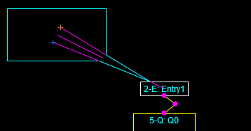
The following steps are taken:
- The center points of the displayGroup and DisplayElement objects are determined (see the central purple line)
- The intersection of the center line and the outer frame of the DisplayElement is calculated (points
ixandiy) - The slope of the center line is determined
- A line perpendicular to the center line and passing through the center point of the DisplayGroup object is constructed
- Points are defined twelve pixels or units from the center point in each direction along the perpendicular line (marked by the blue and orange crosses, points
ax1,ay1andax2,ay2) - The intersection of the two new lines with the border of the DisplayGroup are determined (points
ix1,iy1andix2,iy2) - A triangle from points points
ix,iy,ix1,iy1, andix2,iy2is drawn and filled in black - The two outer lines are drawn in the desired border color
This method handles pointers that cut across a corner as well as any single edge segment. It also doesn’t obscure any text if the text is drawn after everything else. I was happy when I realized I could take this shortcut and not have to worry about corners as a special case. The code for drawing the construction lines shown in the image is commented out above, but left in place so you can follow the action.
The mathematical methods for finding the intersection points are correct but the digital implementation has the infuriating habit of not finding some intersections that actually happen. This is simply because the calculations aren’t accurate enough to always pass the hit tests. Given that we’re using 64-bit reals I find that hard to understand but it is what it is. I’ve traced through a couple of examples and have seen it happen. I have to figure out a way around this problem but have not done so yet. In the meantime I’ve tested to ensure that the process works from all angles, including when the center line is perfectly vertical when the DisplayGroup object is both above and below the DisplayElement target.
Odds and ends:
For now the described process only works with DisplayGroup objects that are not rotated (the process of finding intersection with the DisplayElement frame is general and would handle a rotated target object) but I’m not sure DisplayGroup objects would ever have to be rotated.
For now the described process only “works” when the target DisplayElement is a rectangular component. It would have to be modified for components that are paths, though that process should be relatively straightforward, since the center point of a line segment would be easy to define.
I had to add a parent value to the DisplayGroup object that points back to the simulation component it represents. This was needed so the code in the DisplayGroup object could trace to its parent component object and then to its DisplayElement (graphic) object.
If a component has been selected and highlighted then, for now, its DisplayGroup is drawn as well if it is defined. In the future this is going to require a separate flag since the selection process is going to lead to a menu to allow the user to take different actions or drive other actions based on varying contexts (e.g., run mode, edit mode, etc.).
This method could (and should and will) be generalized to display other types of information, with the primary example being a real-time scrolling graph of one or more state values.
The DisplayGroup objects are drawn after everything else in the 2D scene so they are always on top. I will expand the user hit testing to scan for these objects first when I implement code to allow the user to move, modify, or hide them.
|
1 2 3 4 5 6 7 8 9 10 11 12 13 14 15 16 17 18 19 20 21 22 23 24 25 26 27 28 29 30 31 32 33 34 35 36 37 38 39 40 41 42 43 |
function drawModel() { clearCanvas(globalBackgroundColor); var i; //draw components for (i = 0; i < numComponents; i++) { if (setOfComponents[i].getComponentType() == "Path") { setOfComponents[i].updateGraphic(); setOfComponents[i].graphic.drawBasic(); //setOfComponents[i].drawData(); } else if (setOfComponents[i].getComponentType() != "Arrivals") { setOfComponents[i].updateGraphic(); setOfComponents[i].graphic.drawBasic(); } else if (setOfComponents[i].getComponentType() == "Arrivals") { //setOfComponents[i].drawData(); } } //draw nodes for (i = 0; i < numComponents; i++) { if (setOfComponents[i].getComponentType() == "Path") { setOfComponents[i].graphic.drawNodes(); //setOfComponents[i].drawNodes(); } else if (setOfComponents[i].getComponentType() != "Arrivals") { setOfComponents[i].graphic.drawNodes(); } } //draw entities for (i = 0; i < numComponents; i++) { if (setOfComponents[i].componentType == "Path") { setOfComponents[i].graphic.drawEntities(); //setOfComponents[i].drawEntities(); } else if (setOfComponents[i].componentType != "Arrivals") { setOfComponents[i].graphic.drawEntities(); } } //draw display groups, if active for (i = 0; i < numComponents; i++) { if (typeof setOfComponents[i].graphic !== "undefined") { if (setOfComponents[i].graphic.highlighted) { setOfComponents[i].drawData(); } } } } //drawModel |