
I have described the components of a solution here and have recently realized they should actually be referred to as components of a process. An overall process is composed of a bunch of stations or process blocks, generally joined together by paths or connections. Most components, including queues, are actually special cases of stations or process blocks.
I further described some of the considerations for each station or process block in terms of the items it is connected to using the SIPOC model here. Now I am going to describe the characteristics and actions inside each station or process block.
Before I get to that, however, I need to talk about the language we use to describe everything. I’ve touched on this previously, but further clarification is in order. I want to begin with the idea that a collection of process blocks that make up a complex operation should be referred to as a process or system. Process diagrams are graphical depictions of all the components and connections in graphical form. The BABOK describes several possible variations (section 10.35.3 as of Version 3), but more are possible. Process models include all descriptions of a process, including text and data, of which the diagram is only one. The “P” in SIPOC stands for “Process”, but I call it a station or process block in order to differentiate it from the overall process or system.
Also from the BABOK (section 10.24.1 as of Version 3), “Interface analysis is used to identify where, what, why, when, how, and for whom information is exchanged between solution components or across system boundaries.” This is a pretty good description, but it reflects a bit of a bias of the practice of business analysis as being mainly targeted to the creation and modification of IT systems. (As I understand it, Watermark Learning makes this interpretation explicit in its study materials.) I feel this is far too narrow, and that many systems business analysts and other practitioners will also work on systems with physical components (think retail operations for just one possible application). As an engineer I always wanted to combine mechanical (physical) and computer systems, so I have always thought of process analysis in a very general way. The bottom line is that describing interfaces as being between components within a process or system and across boundaries between processes or systems is the correct and clear understanding.
With that out of the way, let’s get to the subject of this article.
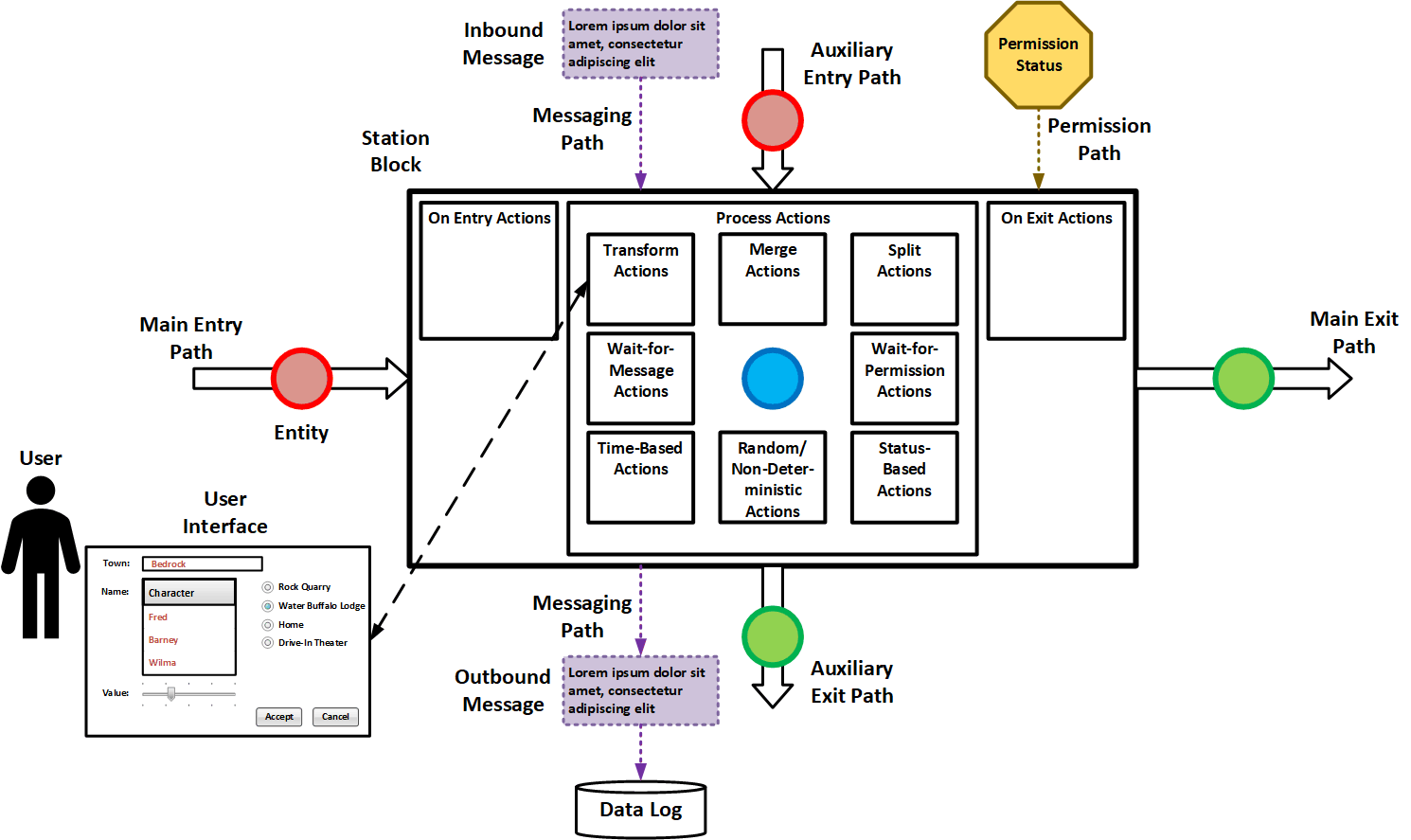
A Station can be simple or as complicated as you would like and a queue almost as much so. A lot of standard features should be included so these elements can become building blocks of arbitrarily complex systems. The difference between a station and a queue is kind of academic. A station is primarily about transformation and decision while a queue is primarily about waiting. That said, entities can wait in stations for various reasons and transformations can happen in queues. This is especially true of non-FIFO queues where transformations can happen over time.
Almost all components can have both physical and informational components. They can be combined in any way that makes sense. It is usually easier to think in terms of entities being discrete, meaning they are always specific, bounded, identifiable, physical objects or packets of information. However, the same analysis can also be performed on continuous entities, which generally involve fluids or bulk solids. Analysis of the latter is generally the province of engineers and scientists and not business professionals. If it’s easier, just think of all entities being discrete for this discussion.
Let’s look at some standard characteristics and actions that might happen in a process block, queue, or other component. Other types of actions are of course possible.
On Entry Action: This can be triggered when any entity enters the component, including the primary entity and any secondary ones. Logging a timestamp for the event is a classic example of this, but many actions are possible.
Transform Action: This involves changing the entering entity in some way. It can involve changing something about the physical nature or configuration of the entity, the data associated with the entity, or a combination of both.
Merge Action: This means that a secondary entity gets joined to the primary entity. Examples include adding a part to an assembly on a production line, adding material to a package on a packing line, adding supplementary data to a larger data record, and so on. On an abstract level, the system representation of the secondary entity may or may not continue to exist in the system.
Split Action: This action involves calving new entities off the primary entity (or splitting or separating flows in a continuous system). This may or may not require creating explicitly new entities.
Send Message Action: This action can be triggered by any other action. It involves sending a bundle of information to an external component or system. The component may or may not be required to wait for a reply before continuing some or all current operations, which is the difference between synchronous and asynchronous is described here.
Wait-for-Message Action: This involves going into a wait state until a specific reply is received. The information received in the reply may guide the actions taken within the component.
Wait-for-Permission Action: This involves waiting for some internal or external permission to be given before one or more internal operations can start or be completed. This is different than the wait-for-message action described directly above in that it involves monitoring for a change of state of some external variable or condition. This difference may be subtle, but it is meaningful. Both actions can be implemented in many different ways.
Wait-for-Resource Action: Certain resources may be needed to complete some of the activities. For example, a dental patient may have their teeth cleaned by a hygienist but then must wait for a dentist to arrive to check for cavities and other conditions, discuss treatment plans, answer questions, and so on. Dentists may come and go many times for complex, multi-step procedures, and alternate seeing multiple patients. Other examples involve having to wait for facilities, machines, or personnel with specific skills and training to become available.
Status-Based Action: This action does or does not occur based on some defined condition or combination of conditions. The test for this action can be triggered by almost any of the other actions.
Time-Based Action: May forms of this action are possible.
- Timers can start at the beginning or end of any other action and trigger most other types of actions when they complete.
- External processes can check entities in a component to see if a specified amount of time has elapsed from a previous action. Two examples are removing perishable items from stock when they reach a specified age, and triggering actions if bills are not paid within windows of, say, 30, 60, or 90 days.
- Different actions can be triggered or statuses changed at specified times during the day, week, month, year, or other time.
Random or Non-Deterministic Action: Some actions are triggered based on random results. Sampling systems may divert entities for further inspections a specified percentage of time.
Complete Sub-Action Action: The completion of some actions may trigger other actions. This is especially important when the action is completed but the main entity is not free to exit the component because some other condition or permission must be fulfilled. The analyst may, for example, want to log the process time and the residence time separately for each entity as is works its way through the component.
On Exit Action: This action may be triggered when any entity leaves the component. Calculating and logging the residence time is a classic example of this.
Component Status Change Action: Other actions may change conditions inside the component or elsewhere. Examples of those changes can involve waste reaching a certain volume; machine tools wearing out and needing to be changed based on number of operations performed, increasing process time, or increased heat or vibration; running out of fuel; and so on.
User Interface Actions: The actions taken can change many conditions or trigger many kinds of actions. They may be associated with other actions, especially those involving transformations. There are many possible types of user interfaces. Examples include direct manual intervention; manipulation of physical controls like switches, button, knobs, and sliders; and manipulations of items on connected or remote screens.
The simplest block might involve having an entity enter, setting a flag on the entity, and then having the entity exit. This effects a very simple transformation on the entity.
Another simple case is one from my discrete-event-simulation demo, where a timestamp is logged when an entity enters, a process time is generated (in a real system that time will usually be fixed or otherwise deterministic but in a model it might be random), the entity resides in the station for that time but no other transformations or calculations are performed (because the point is to evaluate the throughput of the entire system), and a timestamp is logged when the entity exits.
The fact that an operation is completed within a station or process block does not imply or guarantee that the entity will be cleared to leave. It may require permission from the availability of (logical or physical) space in a downstream component or one or more other conditions, singly or in combination.
An entity can pass through a component, it can be merged with other entities, which may involve the destruction of the representation of the joined entities in the system, or it can have other entities split from it, which can involve the creation of additional entities in the system. The result of every action can involve numerous side effects.
Entities may be physical or logical. Physical entities are easy enough to imagine, but logical ones can be messages, data structures, and so on. Any mix of physical and logical entities can enter and leave a component at arbitrary times according to arbitrary rules defined by the designer or discovery analyst. The key is to ensure that the rules are clearly defined and documented.
A station or process component should generally represent a limited number of activities, though activities can occur in parallel, in series, and in combination. It is up to the designer or mapper to choose the most appropriate and accurate representation. Additionally, a single component can have a whole system of sub-components mapped inside it. An example of this is a primary inspection booth at a land border point of entry. At the highest level of abstraction, an entity arrives, sits at the inspection point for a certain amount of time, and gets routed to a further destination. The percentage chance of being routed to the different subsequent components will be a function of the type of entity, time of day, whether other stations are open, and other factors. At a more detailed level of examination, multiple actions can be considered that take place at the inspection booth, all of which can have results of their own, take their own amounts of time and resources, and so on. Obviously, the embedded operations should, when added together, yield the same results as the high-level abstraction. It is up to the analyst to consciously choose the details to consider for each analysis and design effort.
I generally try to structure things to be as clear and modular as possible, but there are no hard and fast guidelines, and doing this well is as much art as science. I hope this modest extension of the existing discussion will help clarify things a little bit and help the reader think of ways to diagram and document actions and operations in a way that enhances clarity, improved communication and analysis, shared understanding, and robust and efficient design.