
The direct link to the latest version is here. Open this in a new window and try resizing it.
While preparing to give a presentation at the CharmCityJS Meetup this Wednesday I spent quite a bit of time investigating the setup of the 3D display, particularly in full screen mode. The first thing I had to do was make the full screen 3D display work again, since I inadvertently broke it when I updated the base HTML last week. Once that was done I set about making it work the way I want even as the user resizes the browser window.
Here’s the base HTML. In full screen 3D mode the normal components are all set to not display and a renderer canvas element is assigned to fill the entire window. Therefore a single wrapper is used to enclose all of the other elements.
|
1 2 3 4 5 6 7 8 9 10 11 12 13 14 15 16 |
<body id="body"> <div id="wrapper"> <canvas id="bcanimation" height="465px" width="420px">The HTML5 Canvas object is not supported on your browser.</canvas> <div class="button_row"> <button id="run_button" onmouseup="runClick()" style="height: 50px; width: 50px" disabled>Run</button> <button id="pause_button" onmouseup="pauseClick()" style="height: 50px; width: 50px" disabled>Pause</button> <button id="step_button" onmouseup="stepClick()" style="height: 50px; width: 154px" disabled>Step</button> <button id="reset_button" onmouseup="resetClick()" style="height: 50px; width: 50px" disabled>Reset</button> <button id="timeOps_button" onmouseup="toggleTimeOpsClick()" style="height: 50px; width: 50px" disabled>Time</button> <button id="multiplier_button" onmouseup="toggleMultiplier()" style="height: 50px; width: 50px; margin-right: 0;" disabled>x1</button> </div> <div id="window3D"></div> <div id="simClock"></div> <textarea id="simProgress"></textarea> </div> ... |
Here’s the code that sets up the 3D display. I originally controlled this with a single variable, virtual3DViewOnly, but realized that making the display 3D and making it stereo/VR could easily be controlled with a separate setting. The stereoVR setting is only used in three places, as it turns out.
If fullScreen3D is set to true the script hides the standard components and attaches a dedicated, full-screen canvas to the window as described. If it is set to false is creates a renderer canvas of a fixed size and attaches it to the target div element. If the stereoVR flag is set then the renderer’s output is piped through an additional transform to produce the stereo display. There are a few other mechanics in place to support changing the size of the window interactively. These are mostly not necessary when not in full screen 3D mode.
|
1 2 3 4 5 6 7 8 9 10 11 12 13 14 15 16 17 18 19 20 21 22 23 24 25 26 27 28 29 30 31 32 33 34 35 36 37 38 39 40 41 42 43 44 45 46 47 48 49 50 51 52 53 54 55 56 57 58 59 60 61 62 63 64 65 66 67 |
//*************************************************************************************** //*** basic 3D setup //*************************************************************************************** //var virtual3DViewOnly = true; //false; var fullScreen3D = true; var stereoVR = true; var renderer; var effect; var scene; var camera; var light; var fovBaseX; var fovBase = 75; function calcFovBaseX(angle,y) { var ang = angle / 180.0 * Math.PI; ang *= 0.5; var x = (y * 0.5) / Math.tan(ang); return x; } function calcFovAngle(height) { var hgt = height * 0.5; hgt /= fovBaseX; var angle = 2.0 * Math.atan(hgt); var ang = angle / Math.PI * 180.0; return ang; } //fovBaseX = calcFovBaseX(75,500); //var k = calcFovAngle(500); function initGraphics3D() { renderer = new THREE.WebGLRenderer({antialias: true, alpha: true}); //if (virtual3DViewOnly) { if (fullScreen3D) { var handleBody = document.getElementById("body"); handleBody.style.margin = "0px"; handleBody.style.overflow = "hidden"; //set wrapper div to not display var handleWrapper = document.getElementById("wrapper"); handleWrapper.style.display = "none"; //set the renderer to cover the entire screen renderer.setSize( window.innerWidth, window.innerHeight ); fovBaseX = calcFovBaseX(fovBase, window.innerHeight); document.body.appendChild( renderer.domElement ); if (stereoVR) { effect = new THREE.StereoEffect(renderer); } } else { renderer.setSize( 420,260 ); fovBaseX = calcFovBaseX(fovBase, 260); var window3D = document.getElementById("window3D"); window3D.appendChild( renderer.domElement ); } renderer.setClearColor("#000000",1); scene = new THREE.Scene(); if (fullScreen3D) { camera = new THREE.PerspectiveCamera( fovBase, window.innerWidth / window.innerHeight, 0.1, 1000 ); } else { camera = new THREE.PerspectiveCamera( fovBase, 420 / 260, 0.1, 1000 ); } light = new THREE.HemisphereLight( 0xeeeeee, 0x888888, 1 ); light.position.set( 0, 300, 0 ); scene.add( light ); } //initGraphics3D |
The other part of the setup involves adding a camera, which defines the viewing frustum. This is the transform that maps the internal 3D representation of objects to the 2D screen. It requires a field of view angle, an aspect ratio, and settings to clip near and far distances from the viewing point. There’s the relevant Three.js documentation. When the size of the window changes the aspect ratio and field of view angle have to change accordingly.
Here’s how changes to the window size are detected and how the camera parameters are updated. I included links to the pages where I found these methods.
|
1 2 3 4 5 6 7 8 9 10 11 12 13 14 15 16 17 18 19 20 21 22 23 24 25 26 27 28 29 30 31 32 33 34 35 36 37 38 39 40 41 42 43 44 45 46 47 48 49 50 51 |
//*************************************************************************************** //*** handle resize events when doing fullScreen3D //*************************************************************************************** //from: http://stackoverflow.com/questions/641857/javascript-window-resize-event /* function: addEvent @param: obj (Object)(Required) - The object which you wish to attach your event to. @param: type (String)(Required) - The type of event you wish to establish. @param: callback (Function)(Required) - The method you wish to be called by your event listener. @param: eventReturn (Boolean)(Optional) - Whether you want the event object returned to your callback method. */ var addEvent = function(obj, type, callback, eventReturn) { if(obj == null || typeof obj === 'undefined') return; if(obj.addEventListener) obj.addEventListener(type, callback, eventReturn ? true : false); else if(obj.attachEvent) obj.attachEvent("on" + type, callback); else obj["on" + type] = callback; }; //An example call to the new addEvent function: var watch = function(evt) { //Older browser versions may return evt.srcElement //Newer browser versions should return evt.currentTarget var dimensions = { height: (evt.srcElement || evt.currentTarget).innerHeight, width: (evt.srcElement || evt.currentTarget).innerWidth }; //https://threejs.org/docs/api/cameras/PerspectiveCamera.html renderer.setSize(dimensions.width, dimensions.height); camera.aspect = dimensions.width / dimensions.height; var newFov = calcFovAngle(dimensions.height); camera.fov = newFov; camera.updateProjectionMatrix(); //you can change the aspect and fov, but must call this to make them effective }; if (fullScreen3D) { addEvent(window, 'resize', watch, true); } |
Setting the aspect ratio as the window size changes is straightforward but recalculating the field of view angle was trickier, and that’s where the calcFovBaseX and calcFovAngle functions come in. The field of view angle is given an initial value (of 75 degrees) in the fovBase variable. This angle is applicable to the initial internal height of the window, in pixels. If the height of the window changes we have to back calculate the new field of view angle that keeps the display the same relative size. (Note that you might not want this behavior, but if you do you have to take steps like those I describe here.)
|
1 2 3 4 5 6 7 8 9 10 11 12 13 14 15 16 17 18 |
function calcFovBaseX(angle,y) { var ang = angle / 180.0 * Math.PI; ang *= 0.5; var x = (y * 0.5) / Math.tan(ang); return x; } function calcFovAngle(height) { var hgt = height * 0.5; hgt /= fovBaseX; var angle = 2.0 * Math.atan(hgt); var ang = angle / Math.PI * 180.0; return ang; } //test to ensure operation is reversible fovBaseX = calcFovBaseX(75,500); //returns 325.8063432103014 var k = calcFovAngle(500); //returns 75! |
In order to keep the displayed scene a constant size we have to keep the viewing location the same distance from the scene. Consider the following figure:
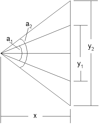
We want to keep the distance (x) from the viewer to the scene constant as we change the height of the window (y), so we have to find the new angle (a2) to go along with a new window height (y2). In order to do that we need to find the constant distance (x) to use. Remembering that the tangent of an angle is the ratio of the height of a right triangle divided by the width of that triangle we know that:
tan( a1 / 2) = (0.5y1) / x
which means that
x = 0.5y1 / tan( a1 / 2).
We know the original values for y, and a1 so we can calculate x using the calcFovBaseX function. Given a new y2 when the screen size changes, and using our constant x, we can find the new fov angle like this:
a2 = 2 atan( 0.5y2 / x)
This calculation is done in the calcFovAngle function. Remember that we have to convert from degrees to radians and back again to do these calculations properly. A good check to make sure we get both functions right is to generate a base x value for a given field of view angle and window height, then feed that window height back into the second function to be sure it returns that same angle.
Once I got all this straightened out it worked like a charm, and it worked if we’re viewing one 3D image or doing so in stereo. Interestingly, the apparent size of the scene is determined based on the initial viewing frustum and the initial window size. The scene will appear to be different sizes based on the initial size of the window, and will not change even if the size of the window is changed. However, a scene initialized in a larger starting window will appear larger than one initialized in a smaller starting window. The apparent size of the scene is also a function of where the camera is located in the global 3D space, and we’ll experiment with that some tomorrow.
Until then, don’t let anyone tell you that trigonometry never comes up in your everyday life. 🙂
Last but not least you may notice that the shape for the Combined component, (C21) is itself rotating about a y-axis drawn through its center. The locations of the components are all defined relative to their center points (on the x-z plane). If doing 3D transforms natively the procedure is to translate the object so the point you want to rotate around is at the origin of the global 3D space, perform the rotation (or scale or skew) operation, and then translate the object back to where you want it. The makers of Three.js know that’s kind of painful, so they hide all those mechanics from the user and allow the code to just say:
|
1 |
this.component3D.rotation.y += 0.01; |
In this example this.component is a reference to one of the shape objects we created and rotation is the total angle of rotation from the original orientation. The y gives access to rotation about the y-axis individually.