
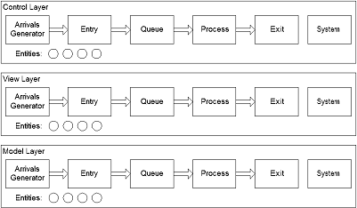
Before adding further complexity to the existing system (read: before adding the capabilities which will make it usable!) I wanted to back up and consider the internal architecture of what I’m building. The goal is something that conforms to the classic Model-View-Controller (MVC) pattern as shown in the figure.
So how does this manifest itself, exactly?
The model layer includes the mechanics that make the system work. There are aspects of this related to the underlying mechanics of the discrete-event system itself, the components that process the entities, and the entities that are processed. The mechanics concern not only how the system “works” but also how it saves and restores models and configurations and other functions. What we’ve created to this point is the discrete-event mechanisms, the components, and the entities, all at a fairly basic level. While there’s a lot more that can be done, conceptually we’ve already included everything we need to create working systems, or at least systems with hard-coded configurations.
Interestingly, the word “model” here has multiple meanings. In MVC parlance the “model” is the functional layer that does the simulation and system-level management. From the user’s point of view the “model” is the representation of an external system of interest that is built up from the various components, entities, and other elements which may be added.
The view layer includes the mechanics that let the user see what’s going on. So far we’ve created objects that display the state of the components, and that information displays the status of the entities indirectly. The data display objects are external to the components, and should be made even more external. These comprise one aspect of the view layer. Another aspect of the view layer will be a system of graphic representations that will be more directed to showing the configuration, connections, and operation of the modeled elements in a more intuitive way. The current setup is very abstract and takes some insight and concentration to follow. A more graphic- or animation-based representation will be easier to watch and understand. It will work the same way as the data display objects but will show the connections between components and the movement and location of the individual entities. Note that this layer is very helpful in understanding, developing, and debugging both the simulation layer (the MVC “model”) and each model’s configuration (the user “model”).
The view layer provides mechanisms to display the state not only the model’s components and entities but also the state of the system as a whole. Possible state information can include the load status of a user “model”, the viability of a user model, the execution time of the system during a run, the execution state of a system (running mode, paused, ended, initialized, outputs compiled and complete, and so on), user permissions, and other factors.
The viability of a user model has to do with its completeness and internal consistency with respect to being able to run, which has to do with any automated verification which can be performed. This is different than a model’s accuracy or suitability with respect to the external system of interest; that requires validation, a process which is difficult to impossible to automate.
The control layer includes the mechanics that let the user control what’s going on. This means controlling the definition, construction, modification, and maintenance of the models as well and the execution, interactions, and outputs from the model. As always, there are aspects of this related to the individual component types, the entity types, and the underlying mechanics of the system. The controls are accessed through the view layer (for example, by right-clicking on a graphic representation of a component or entity) and allow the user to perform CRUD operations on the user “model” elements as well as at the system “model” level.
The MVC pattern usually implies something about how the implementation is accomplished. It could be that the implementations at each layer are highly separated, so that items in each layer are as independent as possible. It could be that items at a lower level don’t have to contain any hooks at all that would allow them to be manipulated by items at a higher level. In practice there are bound to be some hooks, and the question then becomes the form the hooks and connections actually take. Going to the other extreme it might also be possible to construct objects for each component and entity type that provides the functions needed by each layer. That is, each component or entity could contain all of the mechanics it needs to provide functionality at the model, view, and control layer.
There are reasons to go either way and it could be argued that leaning toward horizontal slicing is preferable to tending toward vertical slicing for many reasons. However, design decisions will be made based on many factors, including execution speed, memory footprint, maintainability, modularity, and other considerations. I’m not always a stickler for purity on such issues in the end, but these kinds of problems always benefit from some conscious thought. It could be that the model-level items should be fairly independent but the view- and control-level items should be functionally combined. That seems to be the direction I’m headed.