A Simulationist's Framework
for Business Analysis
Part 10:
Permutations and Traceability
R.P. Churchill
CBAP, PMP, CSPO, CSM, CSDLean Six Sigma Black Belt
www.rpchurchill.com/presentations/TWSLseries/10_Traceability www.rpchurchill.com | Portfolio | Presentations
30 Years of Simulation
Continuous simulation of the heating of a square billet and Discrete-Event simulation of a multi-phase process.
30 Years of Simulation
|
Industries
|
|
|
The Framework:
- Project Planning
- Intended Use
- Assumptions, Capabilities, Limitations, and Risks and Impacts
- Conceptual Model (As-Is State)
- Data Sources, Collection, and Conditioning
- Requirements (To-Be State: Abstract)
- Functional (What it Does)
- Non-Functional (What it Is, plus Maintenance and Governance)
- Design (To-Be State: Detailed)
- Implementation
- Test
- Operation, Usability, and Outputs (Verification)
- Outputs and Fitness for Purpose (Validation)
- Acceptance (Accreditation)
- Project Close
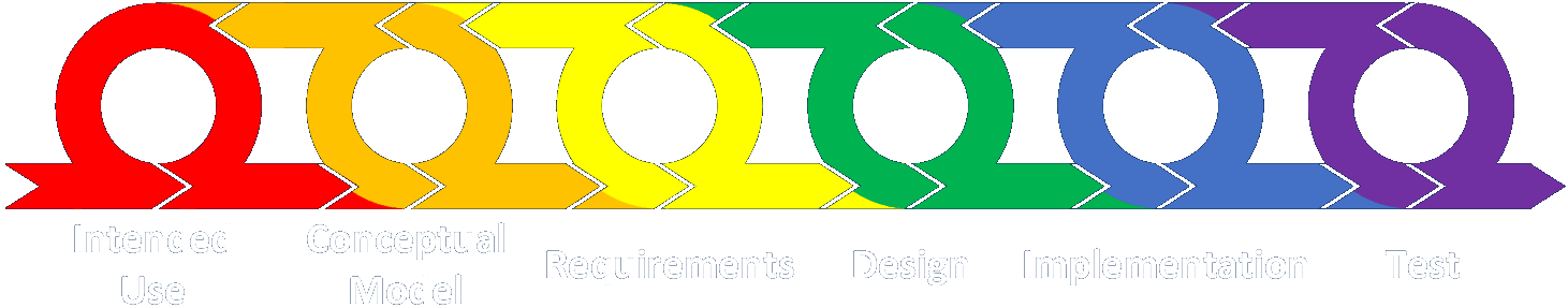
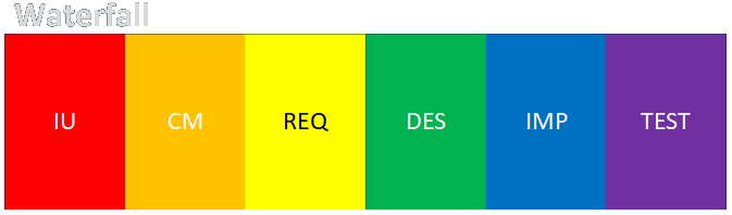
The Framework: Simplified
 Intended Use
 Conceptual Model (As-Is State)
 Data Sources, Collection, and Conditioning
 Requirements (To-Be State: Abstract)
- Functional (What it Does)
- Non-Functional (What it Is, plus Maintenance and Governance)
 Design (To-Be State: Detailed)
 Implementation
 Test
Test- Operation, Usability, and Outputs (Verification)
- Outputs and Fitness for Purpose (Validation)
Customer Feedback Cycle
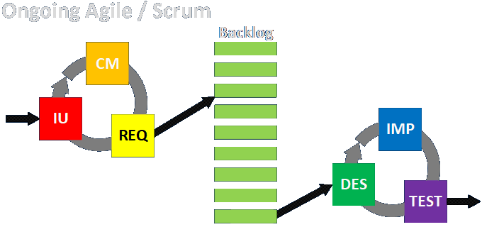
Agile is Dead (in a rigorously formal sense)
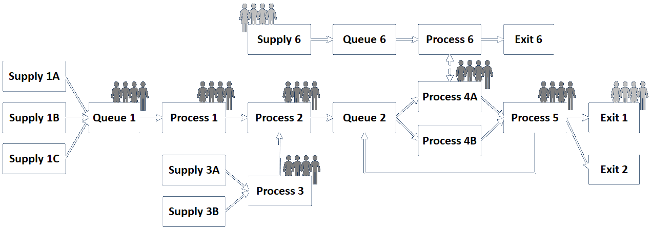
Basic Engagement Structures
Link to detailed discussion.
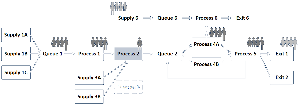
Engagement Structure Variations
Link to detailed discussion.
Engagement vs. System vs. Solution
The engagement is what we do to effect a change that serves customers.
The system is what we analyze and either build or change to serve customers.
The solution is the change we make to serve customers.
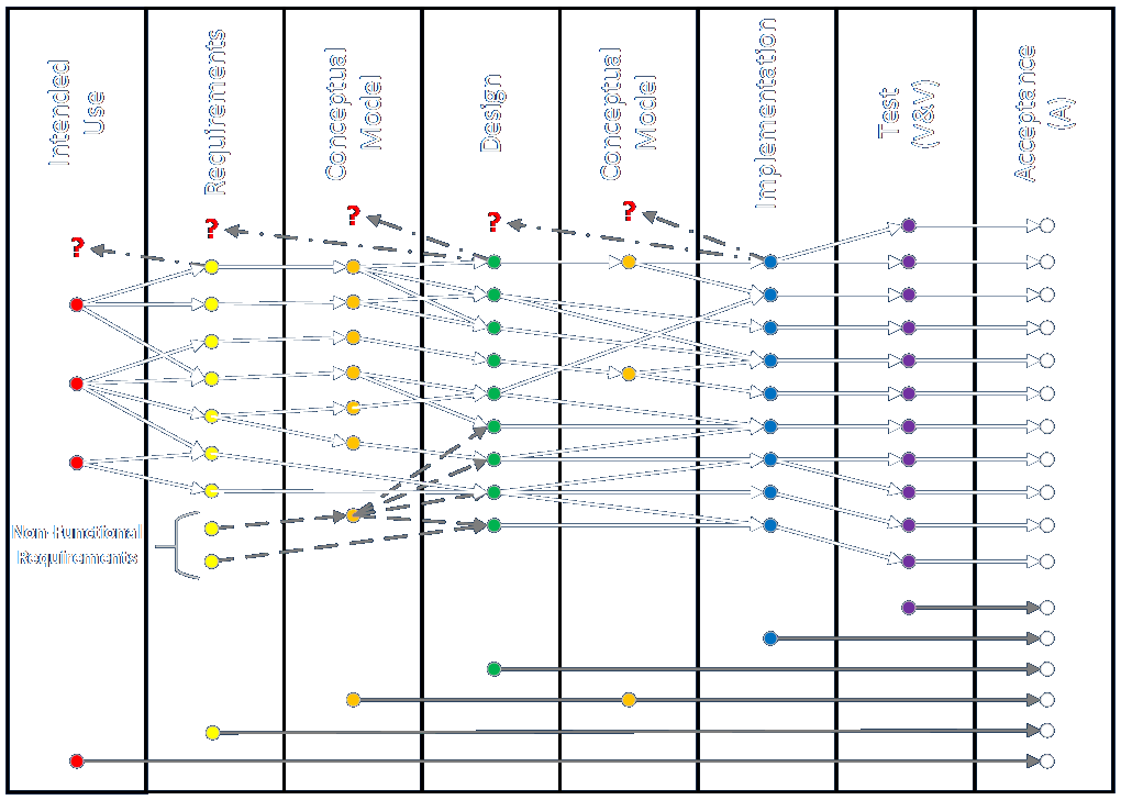
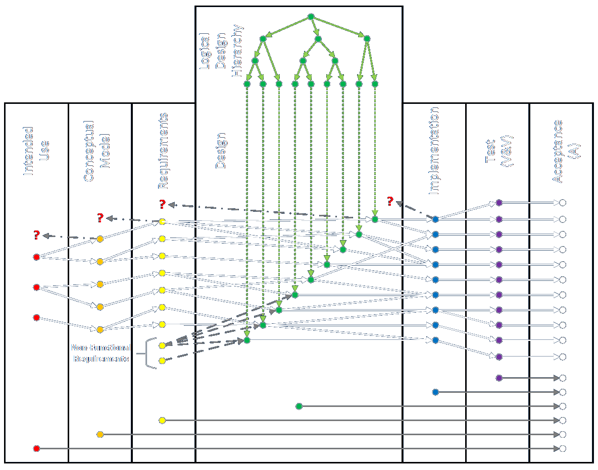
Traceability: Requirements and Otherwise
I usually start from an engagement where an existing system is modified, and then suggest that every item should link through the entire engagement in both directions.
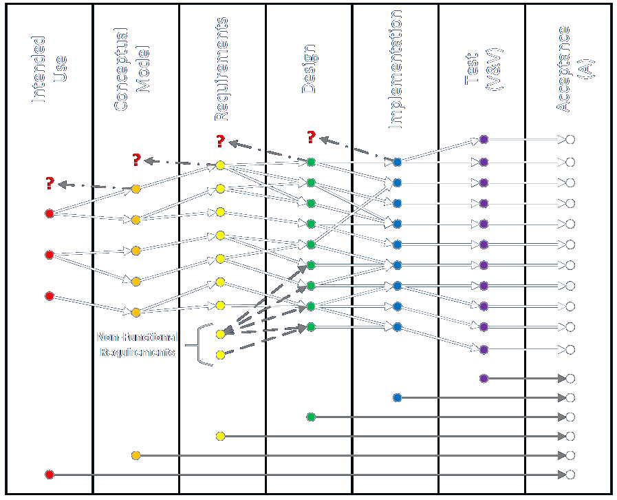
Iterating between phases allows adding or modifying items in previous phases – but not only the previous phase.
In reality, many exceptions and variations are possible.
We could start from non-functional requirements, randomly injected in the middle.
Note that methodology "requirements" are shown separately at the bottom.
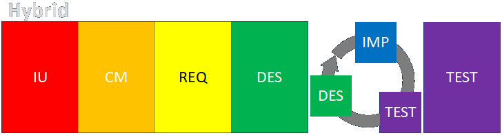
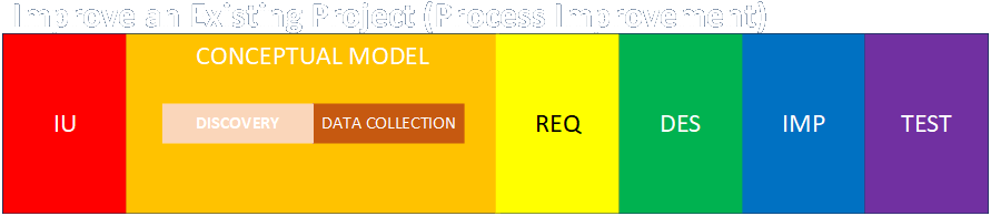
Traceability: Modify vs. New
One of the biggest variations I discuss is whether we're working from an existing system, where we have to build an As-Is model, or whether we're doing something entirely new.
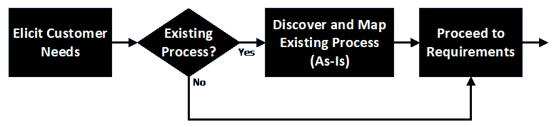
Conceptual modeling happens either way, it's just a question of when.
Link to detailed discussion.
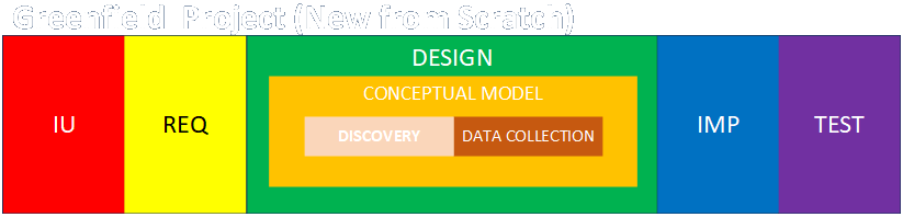
Traceability: Building from Scratch
Here's what a Requirements Traceability Matrix might look like if we aren't starting with an existing system.
The framework is intended to be flexible, but especially in this case.
Iteration between phases is the same as doing conceptual modeling within design... or requirements, or implementation...
Research and discovery (and data collection) may have to be done any time.
Every item doesn't have to link to an item in an adjacent phase.
Traceability: Exceptions to the Rule
Assumptions and simplifications may cause discovered items to be omitted or represented differently.
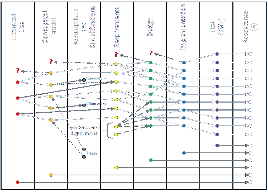
Discovered items may be handled by embedding them in other effects.
Data values may have to be assumed. (Not really backward links.)
Omission or combining may be done in Requirements, instead.
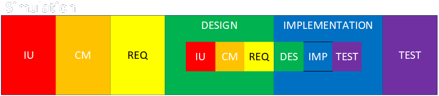
Traceability: More Exceptions to the Rule
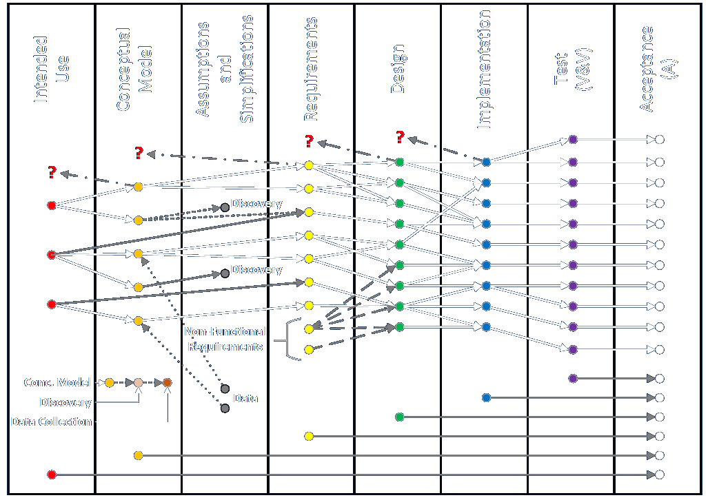
Discovery and data collection usually happen within conceptual modeling — whenever it happens. (Save this thought!)
For example, think about designing on multiple levels for enterprise architecture, or even for a component-based system.
Keeping Track of the Logical Design
The overall design of a solution or system has a hierarchy of its own that must be conceptualized and tracked. How can we do this?
You can imagine (roughly speaking) that the two mappings should correspond in some cross section.
Keeping Track of the Logical Design (continued)
Here's one way to think about doing this.
You could also imagine mapping the respective diagrams on planes intersecting at right angles where the design elements would coincide along the straight line of the intersection.
Now the question becomes, how can we keep track of all this while actually doing the work?
What Work Products Actually Look Like
I've been representing items in all these phases using different colored dots, but what might they actually look like?
Intended Use items tend to be expressed as relatively short declarative statements in text.
Conceptual Model items consist of all artifacts from discovery and data collection including schematics, pictures, figures, layouts, lists, tables, statistical summaries, text descriptions of various lengths, tables, documents, outlines, specifications, manuals, and so on.
Requirements items usually are expressed in text, but may include multiple parts, may or may not be expressed as user stories, may include definition of done and acceptability criteria. This can be supplemented by drawings and other items from the list above.
Design items can come in as may forms as listed in conceptual modeling above, but from the point of view of what is to come.
Implementation items mostly come in the form of progress reports and statements of done-ness and resource availability.
Test items vary as widely as the kinds of tests that are performed. These include unit tests and tests for performance, usability, accuracy, robustness, recoverability, uptime, responsiveness and so on. They can be automated or manual, involve binary yes/no outcomes or more nebulous expert judgments, and embody both verification and validation. They may be performed in a wide variety of IT, management, physical, architectural, and organizational environments.
Other Considerations for Tracking
I generally conceive of Trace Matrix elements of the problem, system, or solution, and less about tasks that need to be performed. That said, my standard RTM representation includes methodological requirements, so a parallel system of work items can be used in addition to documenting discovery, requirement, design, or implementation items.
Items conveniently represented in items hosted in tracking systems (like Jira, Rally, and so on) can link to more complex artifacts embodying a lot of other information.
Items may be refined or progressively elaborated over time, so a way should be identified to house and represent this complexity. For example, think how items are first expressed as epics, then broken down into features, then detailed as tasks, and then tested, per the following:
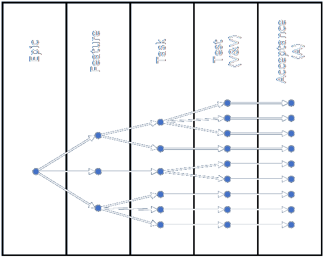
Now further imagine how we can represent the logical design hierarchy in line with the work, and not orthogonal to it as previously shown.
A Basic Tracking Board
Consider the following way work items are often assigned and tracked. A board might look something like this.
- Newly created items are placed in the To Do column announcing that the item is available to be addressed.
- Next, the item is assigned to or claimed by an individual or team, who moves it to the In Work column.
- The work is completed and the item is advanced to the Review column.
- The relevant reviewers examine the item and either sign off on it (and there may be multiple levels of this, as shown in the Approve column) or return it to be worked on more (shown by the backwards arrow).
- When all approvals are granted, the item is finally advanced to the Complete column.
So how do we use something so seemingly simple to track something across many complex phases and layers?
A Tracking Board with Many Layers
First, let's expand the original board a bit to include multiple hierarchical levels:
- As many levels can be included as necessary.
- This representation requires that individual work items have a way to link to parent and child items. This can be accomplished with fields referring to the labels or serial numbers of the linked items. The mechanism should be able to handle multiple parents and children.
- Many systems for tracking work items include ways to reference other items (e.g., via SQL-like queries). Links should ideally be bi-directional, but it is often possible to track items in both directions using uni-directional links and clever queries. Maintaining links can be a hassle.
A Tracking Board with Many Layers (continued)
The status of an item may be dependent on the collective status of linked items.
Some items may move across the board and some may stay in place to represent the logical hierarchy.
Top-level items may represent tasks which result in the creation of many sub-items, (e.g., a single discovery task may result in collection of all items needed to fully and accurately represent a system, product, or environment's As-Is state). This is a way to track both engagement tasks and solution items.
Tracking Across Many Phases
Now imagine that we maintain a separate board for every phase, as shown in this example for requirements.
This example board includes all the features previously discussed, but now let's highlight two extra features.
The rightmost, right-pointing arrow represents a pointer to the next phase (which in our case is generally design).
Items moving to the Complete column may automatically trigger creation of matching (linked child) items in the To Do column of the next phase's tracking board.
The stub of the left-pointing left arrow toward the lower left corner (in the To Do column) represents linkage to the previous phase.
The left-pointing arrows in the center represent the process of iterative work, review, and adjustment within the phase.
Tracking Across Many Phases (continued)
The design, implementation, and test phases work the same way.
- Multi-level breakdowns of items can be represented in every phase, for whatever reasons make sense.
- Individual design items may require numerous implementation elements, for example. And implementation elements may be subject to many different kinds of tests.
- Lowest-level items can be part of numerous higher-level items within a given phase (e.g., an implementation item might be part of a UI concept and an Undo concept).
Tracking Across Many Phases (continued)
The intended use phase is usually pretty simple. Using a more complex representation is certainly possible if needed.
Tracking Across Many Phases (continued)
The conceptual modeling phase might be a little different, as it includes both discovery and data collection activities, each of which may be tracked separately.
The discovery and data collection activities can replace the conceptual model activity completely, and these activities can be inserted wherever needed in the larger tracking structure.
Odds and Ends
Not every item needs to be tracked every way through its entire life cycle if it doesn't make sense. In CI/CD environments the location of the element under test (e.g., a microservice with a new or modified function) may move through multiple test environments on its way to production release. The status and location of the element gives all the information needed, and this may or may not need to be tracked in the way I outline here — at least in the test phase.
Very complex systems should be broken down and managed and tracked as sub-units, each with their own set of tracking boards. One or more levels of integration boards may be used to track the aggregation of components into the final whole. Interfaces between components should be as simple as possible — but no simpler.
The entire RTM should siilarly be represented in the simplest way possible. If Excel will work, use that. If a simplified setup can be effected in Jira, use that. Maintaining full traceability is usually regarded as being difficult and expensive. I propose this method as one that makes the process as simple and clear as I can think of.
This presentation and other information can be found at my website:
E-mail: bob@rpchurchill.com
LinkedIn: linkedin.com/in/robertpchurchill