Nuclear Power Plant Training Simulators
The NRC mandated that all U.S. nuclear plant had to procure site-specific, full-scope, plant training simulators by some point in the early 90s. I worked as a thermo-hydraulic modeler on large teams of engineers and programmers who built the software for them. The software was hosted on Gould/Encore SEL 32/8000-9000 series computers featuring four CPUs and a system of shared memory. A number of different processes ran on each of the CPUs including I/O with the thousands of physical controls and indicators on the duplicate control room panels, "handlers" that processed the operation of standard elements like valves, bistables, and switches in a standard way, and electrical and fluid models that simulated the flows of power, information, fluids, and heat energy through the plant and its interior environment. The system administrators handled the operating environment, configuration of shared memory (DATAPOOL, which held the state variables that were maintained between time steps, variables that did not need to be maintained or shared were just declared locally within each system subroutine), build tools and processes, and handlers. A librarian managed the thousands of technical documents we recieved from the plant that included drawings, instrumentation and logic schemes, and technical and operating manuals for all of the equipment. These were copies of every original document from each plant we modeled. The hardware technicians built and maintained the physical panels and the connection to the computer systems. Project managers and analysts worked with the customer to review the plant's physical components to determine the scope of what would and would not be modeled. That determination was based on whether the component was used in normal operations that might be controlled by or affect the indication of some element on one of the control panels. Items like sample ports and cleanout loops that were only used during offline maintenance were judged to be out of scope. The test engineers wrote test scripts that exercised every component of the plant that was modeled and could affect what and operator could see or do. Experienced plant operators ran the simulations, carried out the tests, and helped the various developers understand each plant and the mindset of a plant operator. The electrical and fluid modelers used similar mathematical and programming techniques to simulate the operation of the individual plant systems they were assigned.
I worked as a fluid modeler, writing subroutines that simulated the fluid and head flows and state changes in various plant systems. Most of the fluid systems modeled the state of fluid and energy "in-the-pipe" while others modeled different collections of rooms within the containment. Other fluid systems modeled external cooling towers and their interaction with the environment. At the beginning of a project an integrated team would visit the plant to record the baseline, steady state readings of every control panel setting and indication under normal operation, and I got to do that for one of the plants. We also spent a week taking an operator training course that described many of the plant's systems to us.
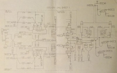
Fluid modelers were given documentation for each system that outlined its scope, the connection points to other systems, the controls it had to respond to and indicators it had to drive. The modelers would then conduct research through the library of documentation, supplemented by clarifications from the customer, to determine the details of the layout, volume, shapes, pressure losses, transfer coefficients, and other physical and operational parameters of each system. The modelers worked with each other to negotiate the type of interface they were going to implement across each connection point between models. Examples for fluid models might be one-way flow or pressure-admittance, and they would agree on the variable names to be used. Leaks from pipes would be modeled as pseudo-pipes that would connect a contained fluid system to a room. If a bunch of hot, pressurized water escaped from a closed system it would probably flash to steam in an open room, triggering a raft of high temperature and possibly radiation alarms. These models had to consider the mass and state of water, non-condensible gases, concentrations of boron and different kinds of radiation, the total amount of thermodynamic energy, and so on in each sub-region or node in a model as well and flows through the connections between them, and there had to be named variables and overlapping contiguous arrays available to access each.
Once the modeler had gathered all of the required data they would work with the documentation specialists and proofreaders to produce a design document listing all of the governing equations, parameter and initialization values, variable names, interface specifications, and proposed methods of solutions in a specified format. There were naming conventions for all variables that were strictly enforced: first letter for quantity type (e.g., P for pressure, H for enthalpy, R for value position, X for I/O address), three letters for the system designator (e.g., RWU for Reactor Water Cleanup and OGS for Offgas), and the final four letters to describe the location or action represented. This document would then be reviewed by the senior managers and specialists who would either recommend changes or give the go-ahead to write code.
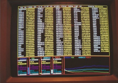
The modeler would then write the code itself. The code itself wasn't all that tricky, the hard part was minimizing the times at the beginning or end of each systems code when it read or wrote the interface and state variables, and how the matrix solutions were implemented. Once there was some code in place the modeler could begin testing. When the modeler was satisfied that things were working well enough they would start working with the larger team on integration testing. The interesting thing here was that having the documentation and governing equations approved and all of the variables and interfaces set up correctly did not remotely guarantee that the model solution was going to work. This is the difference between verification and validation. Verification demonstrates that the pieces are in place while validation demonstrates that the pieces do what they are supposed to in terms of the operational need, which in this case was to accurately represent the state of dynamically operating plant fluid system.
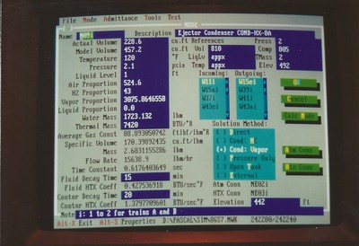
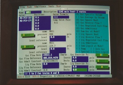
In order to learn how to make one of my complicated systems work, and because Borland had released Turbo Pascal 5.5 with objects (and later version 6 with Turbo Vision, an early text-based, object oriented user interface and container framework), I built a graphical test bed on my own PC. This allowed me to experiment with implementations (in Pascal) that I would implement on the simulator hardware (in FORTRAN) but without requiring use of the simulator. The concept was to reproduce the ability to run a single program on its own while monitoring how the state variables changed during each time step. A special terminal made by Aydin could display far more variables at one time than a normal 80x25 text monitor so that's the look I went for. It was utilitarian but effective, and obviously I expanded the idea quite a lot over the years.
One of the models required a much more complex solution than was originally envisioned and I got a career's worth of education learning how to do it with very little guidance. In addition to making my own test bed for code I also found it necessary to automate the process of generating documentation. This meant creating a program that allowed me to enter data about all the nodes and connections between them, their names, their physical locations and volumes, their initial conditions (mass, energy, composition, state), control inputs and outputs, solution methods, and documentation references for all of it. This information could then be used to automatically generate the governing equations in the specified format, create the variable names and DATAPOOL listings, and calculate the required coefficients. The program would also do things like determine the initial state of each node based on what was known about the conditions there. Since this was a multi-phase (liquid and steam), multi-component (water and non-condensible gases) model the quality, mass, and total energy of each node had to be calculated. The model was also fascinating because the temperatures, pressures, and relative compositions covered the widest range of any system in the entire plant and may have incorporated more unique physical processes and types of equipment than any other system as well. Creating this program saved hundreds of hours of work retyping and reformatting the documentation in response to the many requests for changes as the solution evolved.