Bricmont, Inc. (later acquired by Andritz) – Pittsburgh, PA 1994–2000
Manager of Level 2 Projects, Control System Engineer
Designed, implemented, and serviced Level 2 model-predictive supervisory temperature control and material handling systems for steel reheat and induction melting furnaces worldwide.
- Completely redesigned Level 2 supervisory control software. Migrated department to faster/cheaper systems and introduced new development tools.
- Systems featured 1D and 2D real-time finite element thermal simulations; 2D and 3D GUIs; communications with other processes; and archiving and display of historical data.
- Systems improved steel quality and saved 10%+ on fuel costs.
- Commissioned numerous systems in the United States, Canada, Mexico, South Korea, and Thailand, and served as on-site service representative.
One of my ex-Westinghouse colleagues became a recruiter and hooked me up with Bricmont to replace a fifteen-year incumbent whose first attempted replacement bailed after four days. That was perfect for me. The company knew that people who'd been at Westinghouse Simulators were what they needed because one of them was already working at the company, and that individual sat down with me the first day and gave me the basics of how they did the thermal equations in their analysis.
That was just about all the introduction I needed.
My predecessor's code had the virtue of working effectively but it lacked a few other virtues, like being documented, maintainable, or, when it came to the thermodynamic calculations, even remotely intelligible. After trying to tease it apart for about four hours I tossed it and started writing my own. My first discovery was that using the matrix methods I learned at Westinghouse I could produce thermodynamic calculations that ran extremely quickly. Later I was to figure out that I could employ extreme loop unrolling to make the code go about 30 percent faster still. Since the codes I wrote spent more than eighty percent of their run time crunching matrices, there was no point in trying to be clever to speed the up the rest of the code. At that point it was better to just be clear, accurate, documented, and maintainable.
Extreme loop unrolling is basically writing out every calculation explicitly using constant references for array indices. In this way you eliminate the increased time required to calculate the indirect memory addresses of array elements and also the time taken to increment loop variables and jump back in the code. The code was generated by inserting write statements into the matrix calculation code that wrote out the desired code statements with the indices written as constants. The compiler would treat a statically-allocated array element reference as a direct address in memory. Open the file, run a matrix calculation one time, close the file, copy the file text into a subroutine somewhere, done. I generated code this way for Pascal, FORTRAN, and C/C++ language applications. A one-dimensional solution consisting of seven nodes through a two-inch thick slab needed only a seven-by-two element matrix, the unrolled solution for which was about fifteen lines. A two-dimensional cross-section of twenty-one by seven nodes across a billet or beam blank required a 127 by 8 matrix, the unrolled code for which solution was about ten thousand lines. You can see how nice it was to be able to generate that kind of code automatically.
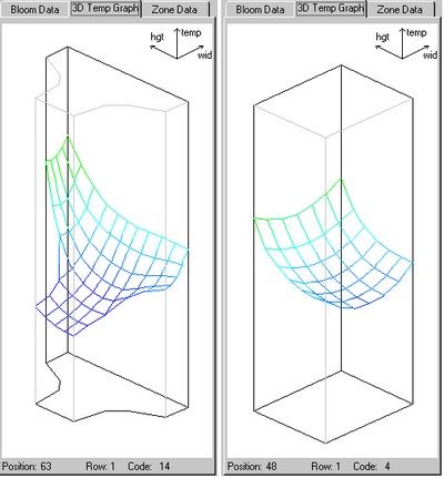
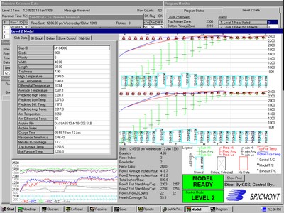
The model UI included these graphics to show the cross-sectional heating of a selected workpiece. The one on the right is a square billet while the one one the left is half of a beam blank, which is assumed to heat symmetrically. I probably should have mirrored the other half to make it more clear but that didn't fit the available panel well. The side to the lower right is the bottom of each workpiece, which is always sitting on the walking hearth. The graphs show that the pieces are heating more quickly from the top and sides.
The company made two basic types of furnaces. One kind heated thin-cast slabs which entered the furnace directly from the caster. These were called roller hearth furnaces or, more commonly, tunnel furnaces. The slabs would be about two inches thick, a bit over a meter wide, and up to about fifty meters in length. Even though the steel was still yellow hot it maintained enough stiffness that it wouldn't droop or sag as the leading or trailing edge of the slab moved across water-cooled rollers that were about half a meter in diameter and about a meter and a half apart. The furnace burners were mounted in the side walls both above and below the slab. The caster would pour a continuous slab which would be cut into sections as it flowed directly into the furnace. The furnaces themselves could be up to 250 meters long, or over 800 feet. These furnaces were not only meant to ensure that slabs were properly heated for rolling, they also served as buffers between the slower-moving casters and the faster-moving rolling mill. Some mills had only a single line but most were built so a second could be installed. The first caster and furnace would be installed directly in line with the rolling mill while the second would be set up in parallel a short distance away. In the case of dual lines a section of each furnace would have to move to allow slabs to be transferred from the second line to the first line so they can be rolled. That was accomplished by either sections that swivel or sections that shuttle. Seeing those movements in person is impressive. If nothing goes wrong, one caster will complete a pour while the other caster is being set up for a new pour, so steel is continually being generated and rolled. If something does go wrong, the furnaces are long enough to be able to keep accepting cast slabs until all sections of the furnaces fill up. If the mill is still not able to run at that point, the cast would have to be aborted. That is an expensive proposition which mills try to avoid for obvious reasons. One of the ways to avoid or at least delay such an outcome is to slow a caster down as the furnace fills up. If a cast does have to be aborted the ladle stops pouring and the chopper simply cuts the remainder of the cast into sections, which drop into a pit between the caster and furnace. These sections of slab then have to be pulled out by electro-magnetic crane (it was always fun to see the pictures on CRT displays warp and go purple when those things went close by under power) and sent back to be remelted. If you've ever seen a flatbed truck with coils of steel chained to it, that's what these mills made.
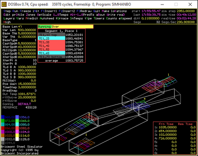
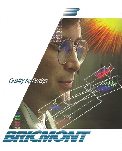
My PC simulation of a two-line tunnel furnace with swivels was visually arresting and was featured on the cover of one of the company's brochures. Alas, they used a colleague's face for the brochure, but the marketing video used my face with the running model reflecting in my glasses. Ha ha, I was famous! The temperature profiles shown on the slabs represents seven layers from the top of the slab to the bottom, on the center line of the slab widthwise, placed every five meters along the length of the slab. It was assumed that all heating was from the top and bottom and conduction across the width and length could be neglected. Workpieces in other types of furnaces did consider conduction in two directions. I got the idea for displaying the temperature profiles this way from an animated sound spectrum display I saw in an IBM commercial, and from a graph of the brightness of a binary star system I'd seen in Omni or a similar magazine.
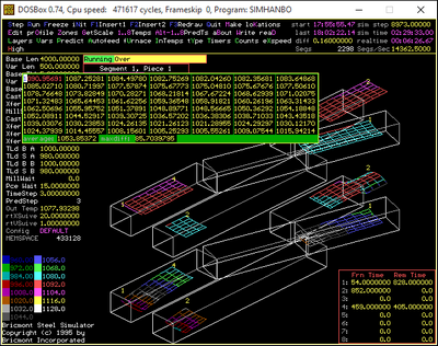
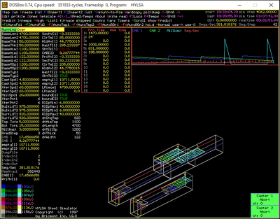
The PC simulations were written in one of Borland's Pascal products, and were used to prove out the code that would be implemented on DEC Vax or Alpha machines in Fortran or C++. The left shot is a two-line swiveling tunnel furnace with both current and predicted temperatures shown graphically, superimposed on the slabs as they moved through the furnace. The right shot is a two-line tunnel furnace with shuttles, with only the current temperatures shown. The movement rules for the shuttles were much more difficult to work out. The right item also represents an evolution in the details I continued to add to the test platform. The customers liked these simulations so much they became formal deliverables that were used for operations research as well as code testing.
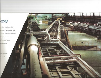
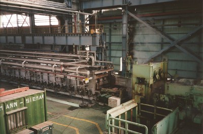
The tunnel furnaces could be up to 800 feet long. The one shown is a two-line swiveling furnace in South Korea. A separate caster feeds each line of the furnace; the swiveling sections are used to transfer slabs from Line 2 to Line 1, in line with the single rolling mill. The right shot shows the discharge end of the furnace. One of the acceptance tests we had to pass was ensuring that the model calculated the same temperatures for the discharged steel as were measured by a pyrometer mounted near the end of the furnace or held by hand. The steel was so hot that in order to take hand-held measurements we would have to wear special equipment and use a partner's body to shield ourselves from the radiated heat.
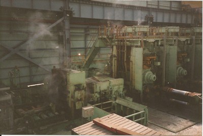
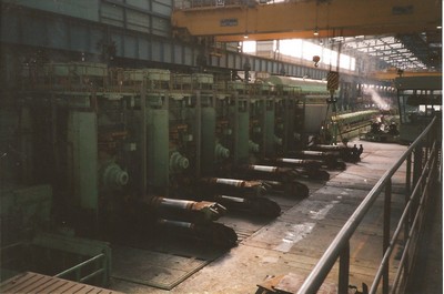
The furnace discharges slabs to the six-stand, continuous rolling mill. The rolls are shown retracted, in preparation for maintenance, inspection, or being changed out. A lot of the hardware for each stand is recessed below floor level.
The other class of furnace heated billets of various shapes and sizes that moved through the furnace perpendicular to their longest dimension. They could be charged and discharged along their length, moving into and out of the furnace on rollers through small openings, or they could be charged and discharged perpendicular to their length. The pieces are moved through these furnaces either be being pushed (a hydraulic ram simply pushes the whole rack of billets or slabs through the furnace until they drop out the far end) or walked (sections of the solid hearth or water-cooled support beams are attached to a single carriage which literally picks all the workpieces up off the static hearth or support beams, moves them forward some distance, and then sets them back down before lowering further and returning to the original position. These systems are also pretty impressive to watch. These furnaces are usually fired from the end wall of each section, in the direction opposite to the movement of the slabs, although burners are sometimes mounted in side walls or roofs. Furnaces may also be fired from below the steel, if they are not based on a solid hearth. The advantage of walking furnaces over pusher furnaces is that while they are more complex and expensive, the pieces inside them do not touch, which means they could be heated over a far greater surface area, which means they can be heated more quickly using less fuel. The heat transfer calculations in simulations of these things had to consider what we called the view factor for all surfaces, which defined how much of the furnace's heat was blocked by support beams and neighboring workpieces. Workpieces usually entered the furnace at environmental temperature, but would sometimes still retain significant heat if they had been only recently cast or poured. Another advantage of walking furnaces is they can be fully emptied, while pusher furnaces cannot be.
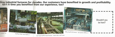
Bricmont made many different types of furnaces; the one toward the left was a walking beam type.
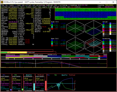
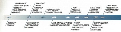
The upper shot shows a PC-based simulation of a walking beam furnace, implemented in the same test platform I started developing on my own at Westinghouse. It had to represent different kinds of information, like the heat number of each billet. The 2D temperature calculations were much more computationally intensive for this type of model, so predicted discharge temperatures could not be calculated for all billets in the furnace. That changed over the years as computers continued to get faster. My success in so greatly speeding these calculations got my work a place on the company timeline for having introduced "Real-Time Process Simulation'.
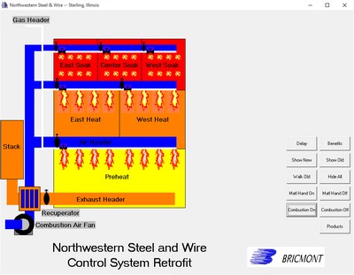
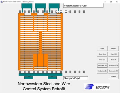
These shots from a presentation I created (Who needs PowerPoint? I wrote a program to animate these!) showed the operation of a walking hearth furnace for which I built and installed a control system upgrade. I gave the presentation at the 1998 Globe-Trotters event of the Association for Iron and Steel Technology (AIST). The right shot shows how the pieces move through the furnace perpendicular to their longest dimension.
The analysis and sales departments worked together to determine the geometry and heating characteristics the furnaces had to have to meet their customers' needs. The design and build department then did the nitty gritty structural and hydraulic work to determine exactly what had to be purchased, fabricated, and installed and then managed the process of doing it. The controls department then designed, built, and installed the systems that made the whole thing work. The Level 0 and Level 1 controls (we referred to both as Level 1, collectively) were based on local controls and sensors connected to cabinets full of electronics which included one or more PLCs (Programmable Logic Controllers). Those were dedicated industrial computers that have excellent, low-level I/O capabilities and were programmed mostly through ladder logic. This mimicked the relays and interlocks of previous analog systems. The Level 1 system was controlled through physical panels in the mill pulpit and on the shop floor, as well as by HMI computers running WonderWare or a similar industrial HMI product. It controlled all of the movement and combustion apparatus and every installation required two or three very talented engineers to implement and install. They had to order custom panels; mount, connect, and configure tons of control circuity; implement the UI and historical logging; and optimize the low-level control strategies. I worked on the Level 2 systems, which were based on a single computer, programmed in some high-level language, that hosted the supervisory control system.
The job of the Level 2 supervisory control system was to optimize the control of furnace temperature and residence time to save fuel and accomplish the heating as quickly and accurately as possible. The variables being controlled were the average temperature and maximum differential temperature of the steel pieces being discharged for rolling. The problem was that there is no way to measure the temperature of the inside of a piece of metal in a furnace. However, the control system gives a modeler enough information to be able to simulate what's going on, so the Level 2 system hosts a simulation which generates the needed control variables and executes the desired control strategy. It also hosts enough communication and ancillary processes to retrieve the information it needs and forward information needed by other systems.
Level 2 systems were hosted on a range of different computers. Tunnel furnace systems all used DEC VAX or Alpha machines for compatibility with the systems that controlled the casters and rolling mills. They ran versions of the VMS operating system and the control and communication programs were written in either FORTRAN or C++. These machines never had any kind of graphical capabilities, but they did support text displays that could refresh without scrolling, so we could generate effective monitoring programs pretty easily. One of the guys I hired to work with me came up with a way to to to a pseudo-animation in text, which showed the position of slabs complete with their IDs and temperature information. One Level 2 colleague was a guru of all things DEC and he always set up those computers, their operating software, and the various communication programs. These often communicated with other systems using a protocol called DecMessageQ. I just wrote the simulation and control strategy and used his programs to decide what data needed to go where.
The first system I actually installed in the field was some sort of Motorola box running Unix and programmed in C. The aforementioned colleague (who was still at the company when I recently visited) and I spent about two weeks somewhere in Mississippi, adapting the communication and tracking parts of my predecessor's code as needed. We turned it on and the simulation and control code seemed to work, so after we verified its operation sufficiently we packed up and left. The first couple of systems I wrote for walker and pusher furnaces were based on DEC machines and programmed in FORTRAN as well, but as soon as PCs and Windows NT seemed sufficiently robust I started using those to host Level 2 systems. They were way cheaper and easier to manage, and they also allowed me to add nice graphics capabilities directly. The Level 2 machines then went from being mysterious curiosities that lived in a back room somewhere to being equal partners to the Level 1 HMIs and sat next to them in the control rooms.
I was working on the control system for a tunnel furnace early in my tenure when I figured out that I had made the process of calculating the temperatures of the slabs so fast that I had time to update the current temperature of each workpiece and also calculate the future temperature for every piece as I simulated their continued movement through the furnace until the furnace was emptied. That was a major revelation to me and I remember my supervisor getting as excited about it as I was. The simulations on tunnel furnaces were pretty quick so this process could be repeated every three or four seconds (remember that computers were much slower at that time), but on walking beam furnaces with complicated cross-sections the time steps might be 30 or 40 seconds. On simple pusher furnaces with one-dimensional models the time step might be ten seconds or so. Previous methods would identify a critical piece in each furnace zone and perform some kind of predictive calculation to figure out how the temperature setpoints should be changed, but it wasn't able to do it very often. With my methods I always had the predicted discharge temperature of every piece available and so could readily carry out a control strategy.
Between the breakthroughs in calculation speed, the improvements in clarity, and the creation of impressive graphics I got a very good reputation within the company. Senior management often brought guests by my office to show off my work and a senior assistant to the president, who originally didn't want to hire me, started going to his guys in the analysis department to ask them why they weren't doing what I was doing. I would be lying if I said I didn't enjoy that.
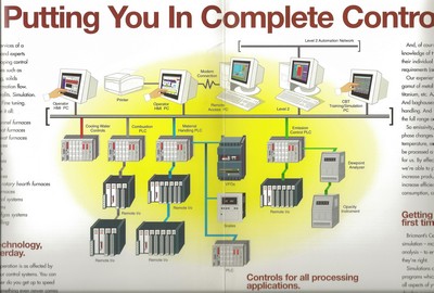
The control systems for all types of furnaces were quite complex and incorporated numerous components. There were way more Level 1 engineers in the controls department; as a Level 2 engineer I had at most one or two colleagues at a time. The Level 2 systems provided supervisory control, control optimization, delay handling, and much of the communications with external systems (caster, rolling mill, plantwide Level 3 system, and others).
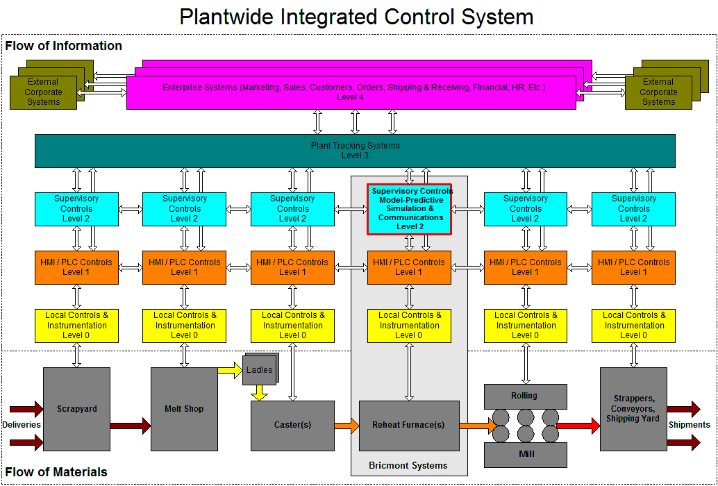
Bricmont's control system components communicated with other plant systems in a station-to-station fashion.
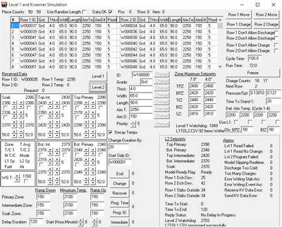
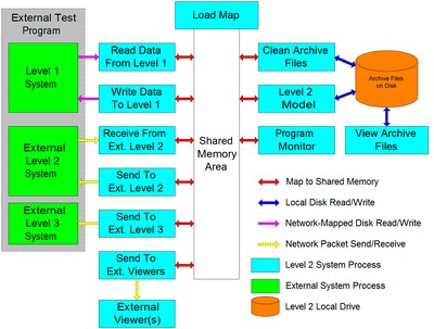
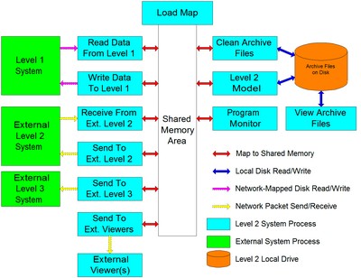
The architecture of the Level 2 systems was the same whether it was running on a DEC workstation or on a PC. Several programs ran independently but communicated internally through shared memory. Communications with external systems used numerous different protocols, including mapped RAM drives, DECMessageQ, FTP, or TCP/IP message. On walker and pusher furnaces I wrote test programs to act like all of the external systems of interest. The test programs provided UI controls and some automated logic to allow the user or logic to modify every possible communicated value. The communication channels were duplicated exactly wherever possible, though occasionally one channel or another would have to be spoofed using a different method.
When added together the code, header, form, and configuration files for some of the PC-based Level 2 projects could get to 50,000 lines, every single one of which I wrote myself in spans of no longer than three months. I also provided detailed, hardbound documentation for each system.

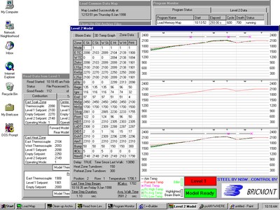
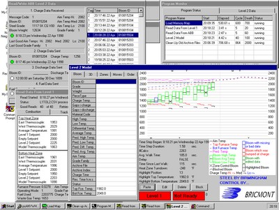
The Level 2 archive programs I wrote could display all parameters and actions for the furnace as well as the full history for every workpiece.
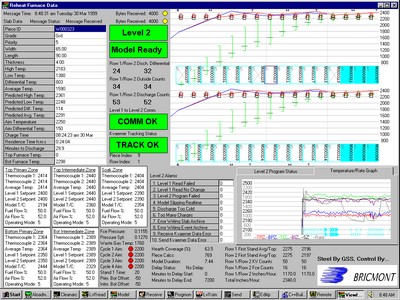
One of the systems I wrote was able to send status messages to external display programs that could run anywhere in the plant. Today this would be done by generating a web page that could be read by a browser.
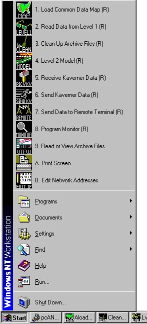
I configured the PC-based Level 2 systems to start and restart all programs automatically, but the user could also restart them by hand if needed. I created all of the icons as well.
The company was still helmed by the founder when I started but it was sold to Inductotherm on February 29th, 1996. Inductotherm was a much larger company, still privately held by its original founder and chairman. They made induction melting furnaces for all kinds of metals, along with the power supplies that provided the energy to those furnaces. They bought Bricmont because we were in a very similar business and because we had a very effective controls department. Some of the controls could be handled in-house well enough, but they were looking for someone who could take over the maintenance and upkeep of the control and HMI software they had been maintaining for a number of years. It was written in Microsoft Visual C++. I was the high-level language guy, so I got the assignment.
Inductotherm was located in Rancocas, NJ, not too far outside Philadelphia, and I made numerous trips there in the following years. The first trip was on Inductotherm's private plane, which was kind of fun. They introduced me to the software and a box full of I/O devices that were read from and written to via serial communications (We referred to the Omega D1000 units as "hockey pucks"). The program was initialized based on a text file which specified the configuration of the attached furnace or furnaces and their respective power supplies. The text was completely modular so files for any word that could appear on screen or in a saved file could be displayed in any language. The program would allocate memory for each furnace specified. For the most part the system could handle running two furnaces, but it would handle three in a limited configuration. The program ran in DOS and got larger as I continued to modify it, so I had to continually rework the boot sequence (remember autoexec.bat and config.sys?) to put more drivers in high memory and leave more space available in low memory.
I was charged with making a modification to the program on the first day, using a program and a compiler I'd never seen and a language I had not seen very much of to that point. Fortunately, the configuration index parameter related to the problem proved to be fairly easy to find in the code and I was successfully able to make my first mod to the program. Over time I got to really learn how the thing worked. Or, more accurately, how the spaghetti was held together. It turned out that the system was originally based on PLC controls but the person who was originally charged with turning the whole thing into a PC program didn't have time to redesign it. Instead he recreated the PLC logic in C code. It was a bit on the funky side, but it was clean and clever and it was cheap to do and it worked. So far, so good. Flash forward ten or more years later, and now the thing has been hacked over by several programmers who started adding and modifying things in very different ways. The core of the code was based on PLC logic, many of the initial add-ons looked like somewhat rational C code, and the most recent add-ons had gotten increasingly anarchic and inconsistent. There were even a couple of new screens that had been developed that could have been added in, but that would have made the maintenance headache just that much larger and I'm pretty sure their inclusion would have made the program too large to run in the memory available on the PCs we were trying to use, no matter how they were configured. I was always able to keep things running and make fixes that worked, but some were more difficult to work out than others.
As we booted up our involvement with the product I primarily worked with two people at Inductotherm. (I also met the chairman and founder, Mr. Hank Rowan, after whom Rowan University is named -- because he bought it!) One was a senior manager who was excellent to work with on an ongoing basis. The other was a very formal gentleman with a PhD in electrical engineering who had managed to emigrate from the Soviet Union before its collapse. We got to ride around with him to visit a few installations so we got an idea of how their systems worked, and the stories he told about what he had done to get out of Russia were both fascinating and a bit scary. As an aside there were a lot of such individuals coming west at that time. I had the pleasure of working with a very interesting PhD in electromagnetics who worked for Bricmont directly, and with whom I developed an idea that resulted in a patent. More on that later.
Inductotherm had me to keep the old system patched together but it was pretty clear they needed a replacement that was written from scratch to free it of memory constraints, handle more I/O and more equipment, and provide a much better UI. A handful of different people worked on that project, which for some reason was written in Visual Basic. I didn't do any of the coding, but I did a lot of advising, mentoring, and design on the project. A number of years after I left Inductotherm decided that Bricmont's support was no longer needed, so they sold the company to a European conglomerate named Andritz, the same company that had previously acquired what used to be Sprout-Bauer. Inductotherm also developed the third generation of the MeltMinder software in-house.
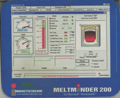
I kept the old Meltminder together while providing guidance to the colleagues who created the new one. The only image I have of what we created is on this mouse pad. The original DOS version featured a much simpler display, though it was perfectly effective.
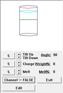
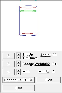
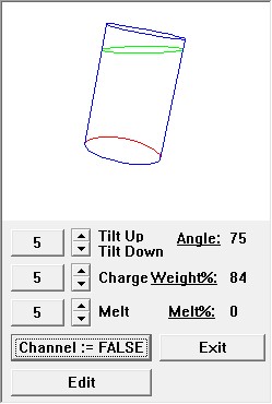
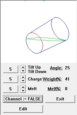
I wrote this utility to experiment with calculations and displays we could add to the new MeltMinder program. It showed loose material being charged and then melted, and then calculated the weight and volume of material as the molten metal was poured out. Calculating the volume of material in a cylinder is easy if no part of the bottom of the vessel is uncovered. If part of the bottom is uncovered, however, the liquid takes the form of an ungula (after the shape of the hooves or feet of certain animals), the volume of which cannot be calculated using a canned formula. I therefore had to code an iterative numerical integration to determine the angle of tilt that matched the volume and weight. I originally did the calculation by slicing parallel to the bottom of the vessel, but after pondering it overnight, the Russian engineer we were driving around with suggested that slicing perpendicular to the bottom might result in slice areas that are simpler to calculate. That's my kind of engineer!
The last new type of project I worked on was a control system for a galvanizing (pickling) line. That system consisted of three sections that heated and cleaned thin-rolled strips so they could be coated by being run through a bath of liquid zinc. The first section was gas fired with open burners. This heated the metal and burned off any surface oils and most of the dirt. The third section of the furnace was also gas fired, but provided indirect heat as flames were confined within metal tubes which themselves heated up and radiated heat to the metal. This allowed the metal to be heated in a controlled atmosphere. The middle section was an induction heating coil. I was never required to finish and install the Rube Goldberg control system I first came up with to run that process. The Russian PhD in electromagnetics I mentioned figured out that the beginning and ending sections of the furnace changed temperature relatively slowly, while the amount of energy that could be added through induction in the middle section could be changed by almost any amount almost instantaneously. He therefore reasoned that we basically shouldn't bother to control the end sections but rather should do all of the active control with the center, induction heating section. I don't know if they ever installed a system using that methodology, either, but it was very clever and Bricmont filed a patent on it, including the names of the three of us that had worked on the project. I know I helped edit the patent application to ensure the claim was both accurate and sufficiently narrow to be unlikely to be challenged, but I didn't find out that it had been accepted until after I had left the company. The only reason I did find out was because I received a solicitation in the mail with offers to buy plaques and other memorabilia with the patent information on it. By now the patent is close to expiration and I would also bet that it has never been challenged or defended. Interestingly, I told this story to a patent lawyer I met and that individual suggested that if all the persons named on the patent were not sufficiently involved in the actual discovery that the patent might, in fact, not be valid. Well, perhaps that's true, and there is a lot that could be said on the subject (see Richard Feynman's story about how he was awarded the patent for the nuclear submarine), but it made for a nice adventure.
I didn't get to any sexy locations with that job, but I did get around quite a lot. I went Monterrey, Mexico on several trips (I was there when my mother died, and had to go home for about three days before returning to finish the job), as well as three visits and 96 days in Tangjin, South Korea, and 63 days in Chonburi (near Pattaya), Thailand. On the latter trip the work was finished after the first week. Then the plant broke. Then we had to wait for testing. I played a lot of golf and stayed out of trouble. I had a great time hanging out with a fun group of expats who made the thing slightly less disastrous and my wife was able to join me for a week early on. I supported a Meltminder fix in Australia. We would communicate by e-mail, but the Internet was not yet robust enough to try to send executable code, so I overnighted attempted fixes and final versions to the plant and the engineer would e-mail back the debug output. When that output showed that the system was working properly the plant could go ahead and start using the release version they already had.
When we were in hardcore development and test mode in the field we typically worked sixty hours a week or more. Seventy- and eighty-hour weeks were not uncommon. There were a lot of trips where I got a nice rhythm going where I was either coding or waiting to review some runtime behavior I could only test when the furnace was "full". I would work at the plant for ten hours or so, get takeout or room service for dinner, work in the room for several more hours, set up a simulation to run overnight, check it in the morning, make another change and re-start the simulation, get breakfast at Waffle House, come back and see how the simulation did, then head to the plant to start the cycle all over again. My first job in Kansas City saw thirty seven straight days of this. I did take a half day off to see a Royals game, but mostly it was just grinding. My work space at the plant was hunched over my laptop, which sat on a cardboard box in the computer closet. On that trip I found a bug in the way Microsoft Fortran Powerstation 32 handled variant records, and found out that the FORTRAN compiler for the VAX didn't generate the same error, so that was interesting. I learned about using regular expressions while doing laundry in the Holiday Inn. After a few years I got tired and had the company pay to clean the few shirts and pairs of jeans I brought. I wouldn't say I'm proud of it but I wrote some code at the bar in that same Holiday Inn, possibly over a couple of beers and definitely dinner. Every now and then we'd get a trip that was just a short business meeting or a situation where we worked mostly office hours, and we always referred to those trips as steak runs. Fortunately, all we usually had to carry was a single suitcase, including steel-toed shoes and a hardhat, and a laptop. It was quite a life, but we got some great work done.
For all the time and challenges, that was one of the three best jobs I've had (the others were at Westinghouse and the first years I was at Regal Decision Systems). The best part was working side-by-side with the Level 1 guys or the engineers who did the other companies' control systems, to work out the communication interfaces and slowly beat things into shape. After killing yourself for weeks on end it was all worth it to finally see properly heated and formed steel rolling out the back door of the plant. No one ever felt bad going home after a successful job, and we never went home from one that wasn't.
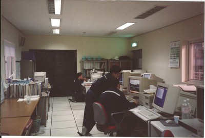
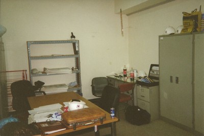
I spent a lot of time in computer rooms and site offices like these. In several cases my desk was a cardboard box wedged in the corner by a computer rack. I identified an error in the way Microsoft FORTRAN Powerstation 32 handled memory in a variant record (or free union) in a little computer closet in a mill in Kansas City.
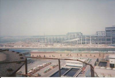
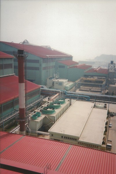
They sheared off the top of a hill, filled in the end of a shallow bay, and built a huge steel manufacturing complex in South Korea. When things got slow near the end of a project it was always fun to explore and climb things.

